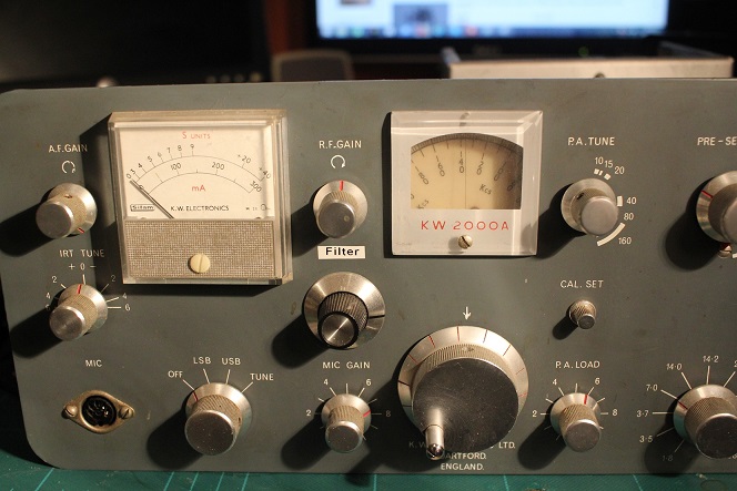
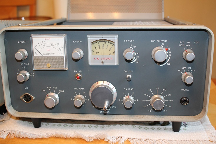
 KW2000A
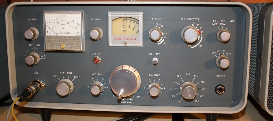
The 2000A had quite a long production run from late 1964 and had a few modifications over its life (adding transmit ALC is one I have identified) . On both my early 2000A 1965/66 schematics there is no TX ALC circuit at all - I can't be certain when the change ocurred but a clearly labelled 1967 diagram shows the additional 3 ALC diodes separately driving the grid of the TX IF Amplifier (V3) with neg bias to reduce the drive. KW issued a modification (MOD 13) sheet for adding ALC to older 2000A units. Also look at my KW2000 page to see the undocumented mod KW made to get over the potential 'splatter' problem that could occur without ALC. The strange VOX plug-in module of the Mk1 is gone and the components moved to the larger main chassis. The classic 2 X 6146 PA configuration makes up the other biggest change. There are other minor changes but they are harder to track down as the schematics changed several times over the life of the radio.
February 2022
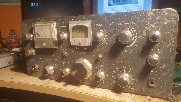
Yet another KW2000 (number 10 I think !). This one came from a batch of 3 from an old ham friend, the other 2 went to my collector friends. As I already had 2 good KW2000As I took the one in the worst cosmetic condition. Front panel paint was in very poor condition and just flaked off if it was touched, the chassis had a lot of surface corrosion marks. The cases of both the radio and PSU were also in a poor condition. First exmamination showed that the radio was complete and the underside was very clean - probably protected from any moisture. Some components were replaced but overall it was in good orrder.
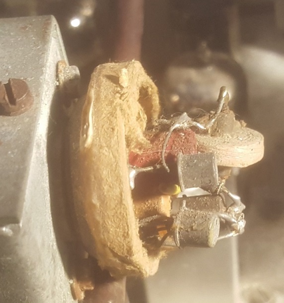
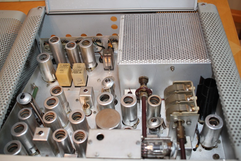
I quickly took the decison that the front panel would have to be taken back to bare metal, and the radio stripped down for a deep clean. Here I found that corrosion had welded some of the knobs onto the control shafts and I was forced to drill out a couple of hex allen screws to remove the front panel. Removal of all the valves, PA covers, relays and crystals meant I could get to work. The ECF82 VFO valve had been replaced by a 2 transistor plug-in circuit that fitted into the B9A valve socket. At this stage I had no idea if it actually worked..it looked a bit rough. The PA compartment revealed a corroded joint on one of the 6146 anode parasitic chokes..it just fell off !.
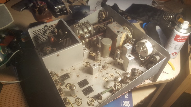
Over several days I cleaned the chassis removed the bodged japanese 4 pin mic connector and sanded the front back to bare metal. I cleaned the valve and relay sockets, the crystals and all the pots and switches. with no shorts on the HT and EHT lines it was time to re-assemble and run it up from a good PSU.
It came up on RX straight away although it soon bacame clear that the 2 main switching relay bases needed more cleaning, once done the receiver showed good performance on 40m, but the rig would not key into transmit. I have been here before - the VOX circuit operates a relay that then keys the 3 relays that put the radio into TX, its in the anode of the VOX valve and was open circuit, swapping the relay from another radio proved the fault. Its a 15K coil 150V relay and they appear to be prone to failure - I had given away my spare a year before !
The radio could now be put into transmit and showed RF output, but it was low and so was the PA standing current. This was the give-away - on 160m one of the PA cathodes is lifted to cut the power down and comply with the 33W input legal limit for UK stations in the 60 and 70s. The switch wafer was so dirty that the valve was out of circuit on every band. I hardwired it to solve the problem and 80 -90W OP was restored. Although the 3 main 12V relays can be keyed directly from the PTT by the addition of one wire, the radio would have no VOX capability and be fiddly to tune up. I decided to try a small 48V DC relay with a series resistor to get to the 15K coil resistance of the original, this worked perfectly and I ended up soldering the relay under the chassis.
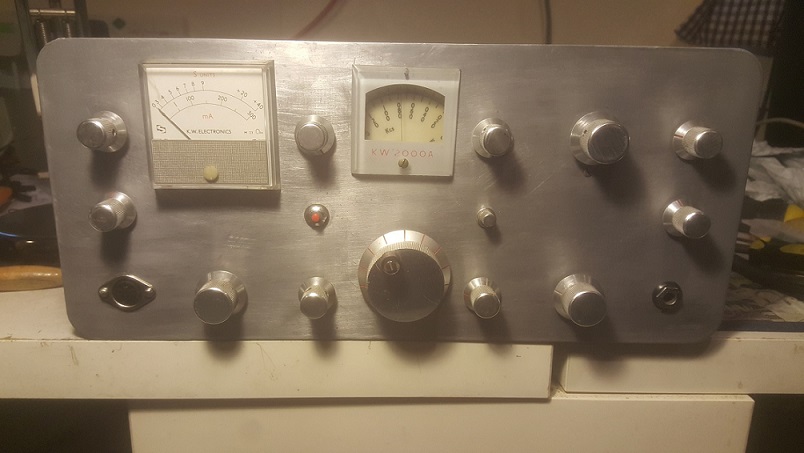
The front panel is more of an issue and one that I have never tackled before - just about any solution would mean the radio would never look original. I may opt for simple lettering and a light paint colour for a one off KW2000A
January 2018 - KW2000A
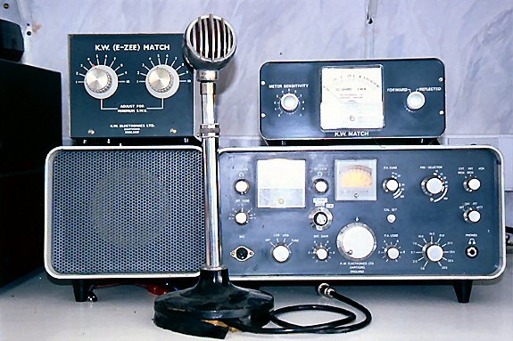
Donated by a friend who was moving house. As I know the 2000 so well I was off and running removing the front panel and various bodges the very next day. A Howes CW and SSB audio filter controlled by a switch in the CAL button position was a quick removal although it had been glued to the chasssis (?). The CAL switch had been added to a bracket inside the radio. For some unknown reason an extra relay had been stuck (with tape) near the output transformer - as usual I had to clean all relays, switches and pots. All the case screws and feet were missing along with the PA valves. I put the PSU to one side as I already had a restored KW2000A PSU. I traced a previos owner from over 20 years ago and he sent me this picture of the radio as it looked back then - an owner before him had put the audio filter in.
 I also removed an audio
transformer in the mic preamp (probably to allow use of low Z
microphones), and changed the resistors that always go very high
in value in these radios.
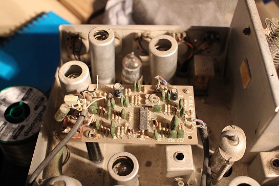
During this initial assessment I found a few dry joints and crystals
held in with cardboard as the holders had worn (easy fix with a small
screwdriver).
I also removed an audio
transformer in the mic preamp (probably to allow use of low Z
microphones), and changed the resistors that always go very high
in value in these radios.
During this initial assessment I found a few dry joints and crystals
held in with cardboard as the holders had worn (easy fix with a small
screwdriver).
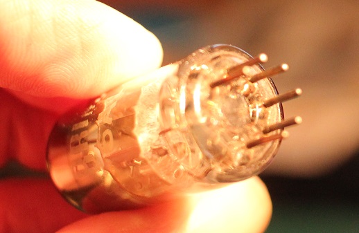
After 8 hours I had removed some of the bodges and got the RX working on one 80m segment A broken pin on the AGC valve (6AL5) and oddly also its valveholder caught me out for 30mins - I ended up just changing the single pin in the valveholder (didnt know you could do that). Proper AGC operation was then restored- but alignment way off and only some of the heterodyne crystals working.
The heterodyne crystal issue had me guessing for an hour - how could some work and others not?..I swapped crystals around to no effect, checked all the component values and scratched my head. After a very careful visual examination of the bandswitch the penny finally dropped - the first and second bandswitch wafers (which switch the het oscillator) were one click out of alignment, so in most positions the crystals were paired up with the wrong coils and trimmers. It was easy to undo the shaft coupler and put it right but it must have been like this for years - the shaft coupler wasn't loose..now the receiver really came to life !!.
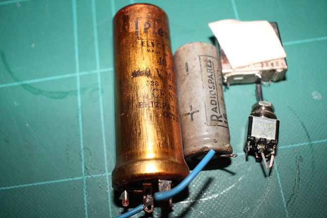
Once it was clear I had a working radio I got to work removing more mods and bodges...2 electrolytics had been grafted in to decouple the HT (althugh the stock radio only actually has one) - both were ancient and one was dated 1960 making it older than the radio. I took out a switch on the back panel and its associated relay (some sort of audio mod). All in all I probably changed over 15 resistors and in reality could have done a lot more - I left those that were around 20% high - none were low in value.
Ovet the next week I found a few more resistors way out of spec, a shorted electrolytic in the mic amp and oddly some missing components. The cathode bypass cap on the TX amplifier before the filter was absent (?), so I put it back.
Another oddity was an added 250pf that appeared to be in parallel with the OP of the mechanical filter - when I lifted it off the gain dropped down. In the end I dropped in another filter and the cap was not required. I assume that the cap across the IF transformer inside the filter can has failed and this quick and dirty bodge restored the gain. Should be an easy fix once I get the old filter open.
There was another capacitor missing across the VFO output and I think its because the OP is a bit low - so VFO refurbishment is probably required - See my KW2000 pages on the taking the VFO apart.
The balanced modulator was very poor on TX - I could not null out the carrier - this required two component changes. One of the 270R resistors either side of the balance pot had gone up to 370R and the beehive trimmer had to be unscrewed all the way out. I changed the 47pf capacitor across the trimmer to 10pf and finally was able to null out the carrier. I then aligned the radio and neautralised the PA valves
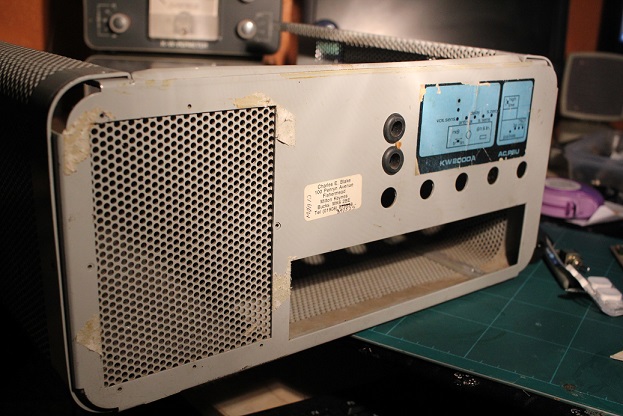
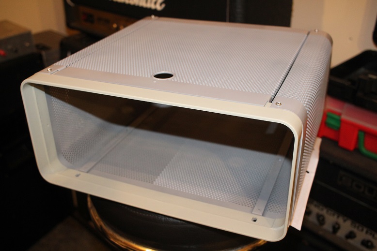
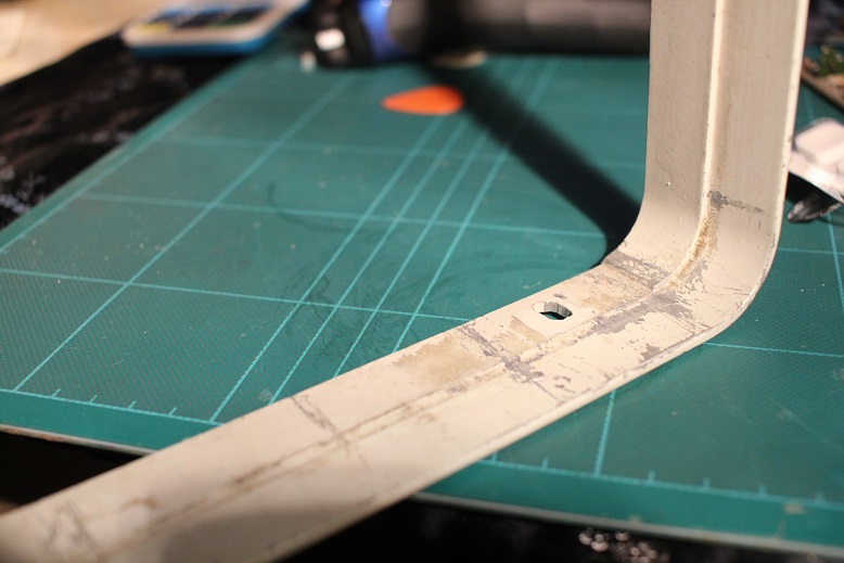
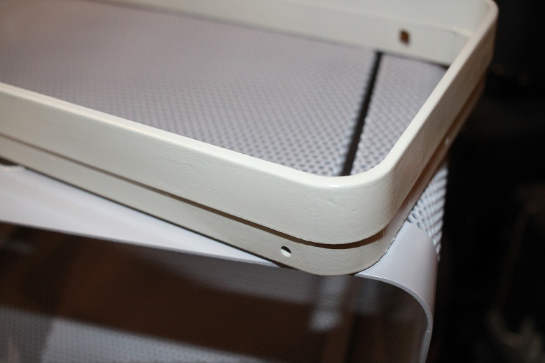
As with most KW 'G line radios' I have seen or worked on, both the bezel and the outer case were in a poor state. The bezel on this one was no exception and had to be rubbed down quite a lot to get rid of the marks and scratches before priming. After the glue, stickers and double sided tape were removed (for a PA fan I suspect) - the case was also rubbed down and primed ready for its top coats. New M4 screws and nuts were used to re-assemble it after the final paint session. I have also remade the blue sticker
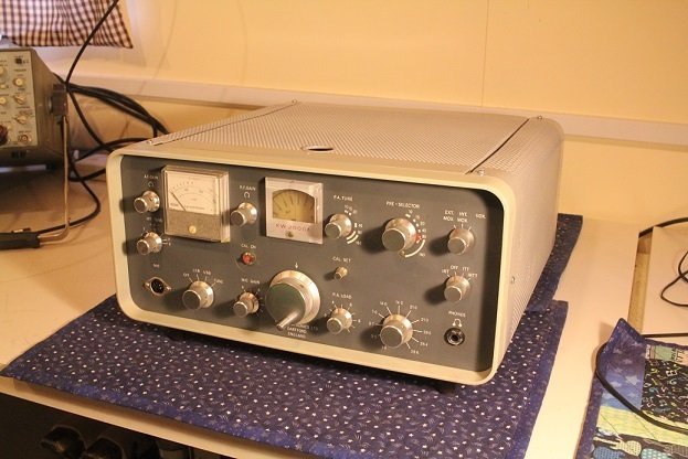
Finally after about 8 days work I have returned the radio to its its original state and working pretty well on the low bands. A pair of used 6146w valves give good output and there is plenty of drive from my favoured Shure 444. Contacts on 40m and 80m report good audio and reasonable VFO stability - there is no ALC on this pre 1967 model so you have to be careful with the audio drive. Of course there is always more to do in any refurbishment, but this is a nice addition to the collection and yet again I am thrilled to bring an unloved KW radio back to such nice electrical and cosmetic condition.
CABINET / BEZEL RE -PAINT
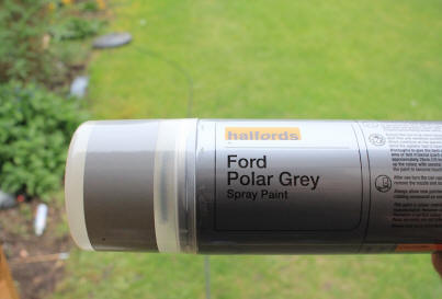
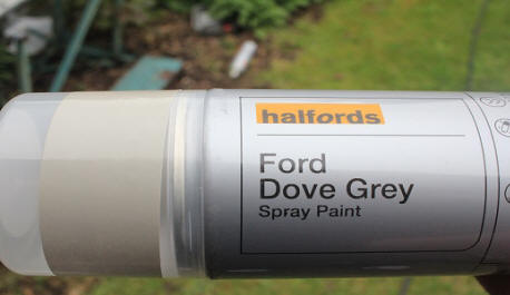
the main case colour is close to Ford Polar Grey, the bezel is lighter and Ford Dove Grey is a very good match - I defy anyone to tell the difference!. I rub down with a light emery paper block soaked in water...and then use 3 light coats of car (automobile) grey primer and then 3 light coats of the top colour..always looks fantastic.
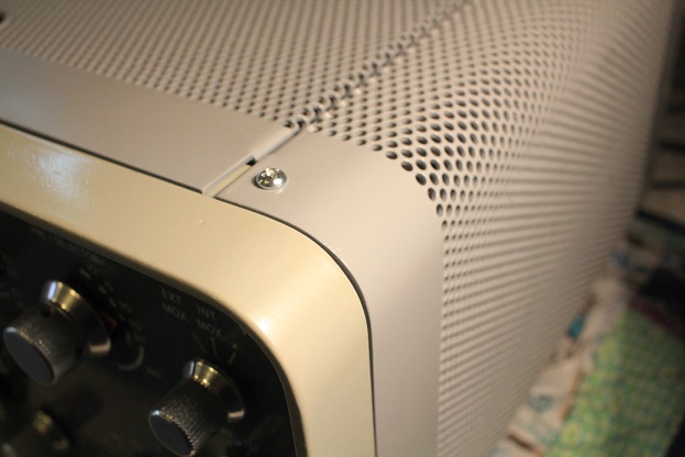
The completed cabinet below shows how good these two colours look
KW 2000A JANUARY 2016
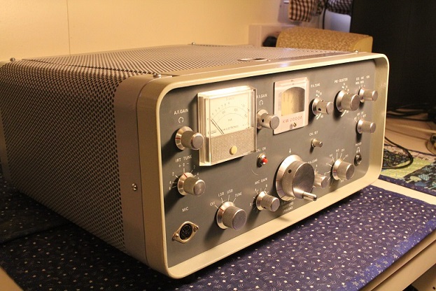
Ebay purchase delivered in Jan 2016 and I was more excited than a kid at Christmas. Opening the boxes revealed a near mint KW2000A with hardly any marks to show its age and the same with the Vespa, The 2000 had been well looked after and had been the subject of a part restoration. I sat stunned in front of them on the kitchen table. Now the hard part.
The KW2000A PSU looked correct but did not appear to match the transceiver - on power up all the voltages checked out, but the radio just gently hissed. On close inspection two tubes appeared to have no heaters, the VFO and Premix..how could this be?, surely all the heaters were wired together.
Emails to KW collector and guru Guy G0UKN followed..he told me those two tubes have a separate heater supply...what??. I had been fault finding with an early Schematic for the KW2000 (not the A,B or E) and this didn't show it. Then the penny started to drop - the Power Supply was for the earlier version of the radio and it didn't have the separate heater supply for the VFO. I traced the wiring and sure enough that was the problem, KW used a 9R dropper resistor in the PSU to get the 12V down to 6v for these two valves. A rummage in the junk box and the radio woke up!
Why the earlier restorer (who had done so much to the radio) missed this, I will never know. Perhaps he too was working from the wrong schematic and just couldn't work it out. Any how back to life and good power out on 40m, 80m amazing !!
Over the next few weeks I started to learn where all the componenets lived in a 2000 and replace more of those damn resistors !
Connect with me today
Call me on 44 (0)7970 190437