 KW201,
KW202, KW
Vespa, KW160, KW Viceroy, KW77, KW Valiant
KW201,
KW202, KW
Vespa, KW160, KW Viceroy, KW77, KW Valiant
 KW started out making separate
transmitter and receivers for 50s UK Hams mostly running AM. The
inspiration and indeed some of the components came from the Italian
Company Geloso, . All this early AM gear was in the larger style that was
to become known by the rather unflattering term of 'Boatanchor'. The KW
Vanguard, Victor and smaller (and rarer) KW Valiant transmitters were
paired with the KW76 (also very rare) and later the KW77 receiver. In
1959/1960 KW
started making their large KW Viceroy range of SSB transmitters. However
things were moving quickly and by the mid 60s KW started to market smaller separates that fitted into its KW2000 'G' Line..starting with
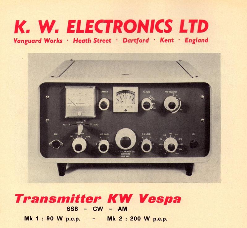
the KW Vespa TX and KW201 RX and ending with the KW202 and KW204. Sadly KW
never got the hang of getting their separates to 'transceive' as a
pair..something the competition had sorted pretty early on.
KW started out making separate
transmitter and receivers for 50s UK Hams mostly running AM. The
inspiration and indeed some of the components came from the Italian
Company Geloso, . All this early AM gear was in the larger style that was
to become known by the rather unflattering term of 'Boatanchor'. The KW
Vanguard, Victor and smaller (and rarer) KW Valiant transmitters were
paired with the KW76 (also very rare) and later the KW77 receiver. In
1959/1960 KW
started making their large KW Viceroy range of SSB transmitters. However
things were moving quickly and by the mid 60s KW started to market smaller separates that fitted into its KW2000 'G' Line..starting with
the KW Vespa TX and KW201 RX and ending with the KW202 and KW204. Sadly KW
never got the hang of getting their separates to 'transceive' as a
pair..something the competition had sorted pretty early on.
KW202 Receiver April 2023
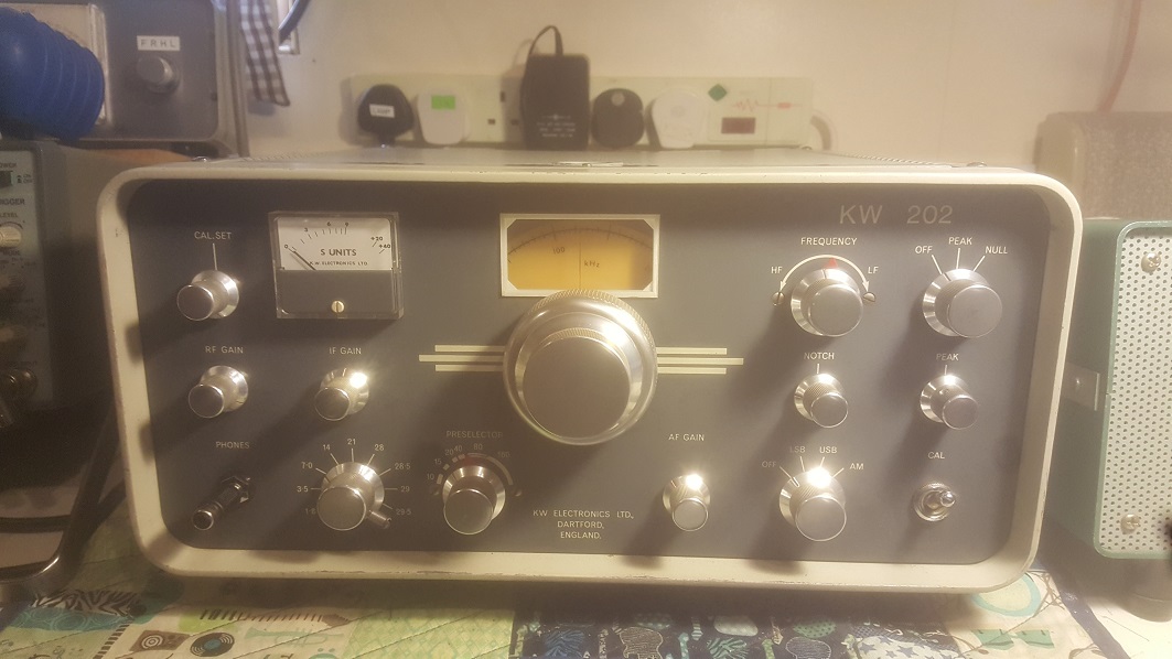
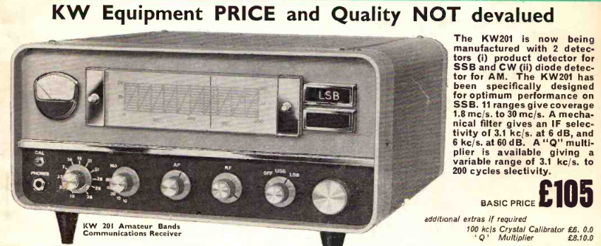
Wasn't really looking for a 202 but one came along from an SK sale and I took it in. In very clean condition with no marks on the front panel (unusual). The 202 was an upgrade to the 1960s KW201 (see further down this page) as a companion to the 204 TX. KW had to get proper 500kHz bands in their gear as the competition was ahead - 200kHz bandspread left too many gaps on some bands. Rather than change the basic design KW just adapated the 201 design (in itself based on the KW2000)...this meant that the 200kHz broadband coupler of the low 1st IF could no longer cope with a 500kHz bandwidth and would have to be tuned in tandem with the VFO. This further meant that the VFO variable cap would need extra sections and wouldn't fit in the VFO box...so it was left open to the air !. The internal speaker of the 201 was removed to make way for the Q multiplier - a welcome addition for CW operation. The poor RF front end of this whole series of KW gear was kept, and the very odd RF/IF/AF gain arrangement appeared. The 500kHz bandspread also meant that the frequency readout resolution is very poor - 5kHz at best. The 3kHz mechanical filter (as on the 201) is a bit too wide for SSB on crowded bands and too narrow for AM. Other than the Q multiplier there are no other useful features.
Another drawback is the inability to allow either VFO on the 202 or 204 to conntrol both units - they had to be 'netted' togther. The US company Drake sorted this years before - KW were way behind the times. All valve receivers were also getting out of date by mid 1971 (and the KW202 wasn't even a very good valve design - not a single transistor or FET in sight !), Trio / Kenwood had brought out the all solid state JR599 and others were waiting in the wings. The 202 was made down to a price point and thats all that mattered.
Aftre a bit of checking and cleaning the receiver came up straight away. Some of the alignment was slightly off and I changed four resistors that were over 50% high. The S meter calibration had been twiddled and some holes in the lid probably meant a speaker was fitted in the past
As a straight SSB receiver its not too bad although sensitivity on 10m band always seems poor with the strange front end design. KW switch out screen resistors of the RF amplifier valve as the bands go up. Some restorers bypass the RF amp cathode resistor for a bit more gain but too much and the valve oscillates !
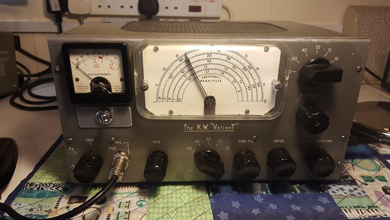
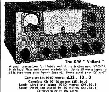
KW Valiant AM Transmitter - May 2018
Another bit of gear that I did not expect to see..they are pretty rare. One of my trader friends spotted this one at the 2018 Blackpool Radio Rally and bought it knowing I was keen to own one. The Valiant was one of 50W input AM transmitters that along with the more popular Vanguard appeared in 1958 and 1959. There was also a less well known 120W input AM TX called the KW Victor. The little Valiant is effectively a KW Vanguard without a Power Supply..most of the circuit is identical. Both have the Geloso 4/102 'signal shifter' driving a single 6146 modulated by a pair of 6L6 tubes - there is an additional 6BW6 PA 'clamp' valve some variants of the KW Vanguard. I wanted a Valiant because I liked the fact that its compact, very light yet still capable of running over 25W OP of proper AM. As is pretty typical of KW the Valiant / Vanguard circuit looks very similar to another companies product - in this case the Geloso transmitters of the same period (G212 and G222). There are subtle differences (Geloso liked 807 tubes) but in general KW have just adapted the design slighly to their own ends.
I particularly like the little bridge
rectifier that allows modulation depth to be measured on the meter (yes
its a Geloso design !). In another oddity the Geloso VFO in the Valiant
is the version with a 6L6 that would be suitable for driving 2 OP tubes.
KW replaced the 6L6 with a lower power 6V6 as they were only driving a
single 6146. The print on the chassis clearly says 6L6 but the KW
documents show the 6V6. Maybe Rowley ordered a lot of these units for
the less popular KW Victor and then realised he could save some money by
changing to a cheaper valve in the Vanguard and Valiant
 .
The clear plastic cover over the Geloso VFO dial always breaks on old KW
gear and there is an innovative solution..and done on this radio. A
Ferrero Rocher 6 pack chocolate box lid is a near prefect fit with just
a couple of holes! - its a fraction too wide but looks good.....I have
bought a spare and eaten the chocs.
.
The clear plastic cover over the Geloso VFO dial always breaks on old KW
gear and there is an innovative solution..and done on this radio. A
Ferrero Rocher 6 pack chocolate box lid is a near prefect fit with just
a couple of holes! - its a fraction too wide but looks good.....I have
bought a spare and eaten the chocs.
The TX came with a suitable Power Supply that was clearly a modified KW2000 model. KW offered no provision for any TX/RX switching on the Valiant..nothing at all. All the HT, antenna and receiver mute switching was entirely down to the customer and I bet some rather weird / wonderful / downright dangerous solutions were dreamt up by hams at the time.
A previous owner of my one sure did like his little 12V relays. He added no fewer than 4 of them - 2 in the TX and 2 in the PSU. He derived 12V DC from the heater chain and used these relays to switch HT rails, RX antenna, RX mute and a spare set. The Belling Lee microphone socket has been replaced with a standard 4 pin one allowing PTT operation - I rewired it to match all my Yaesu gear. I get around 25W out with super audio reports from a Shure 201 microphone..and its great to see the modulation meter swing up to 100%
As an end note I'm not sure why the 2 x 6146 KW Victor was not more popular, 60-70W output of decent AM would seem to have been a good thing back in the day and it was in the KW adverts for nearly 3 years. The Heathkit DX100u is a smilar design and sold pretty well. Perhaps they proved unreliable, too large or too expensive. The KW Vanguard has survived in far greater numbers.
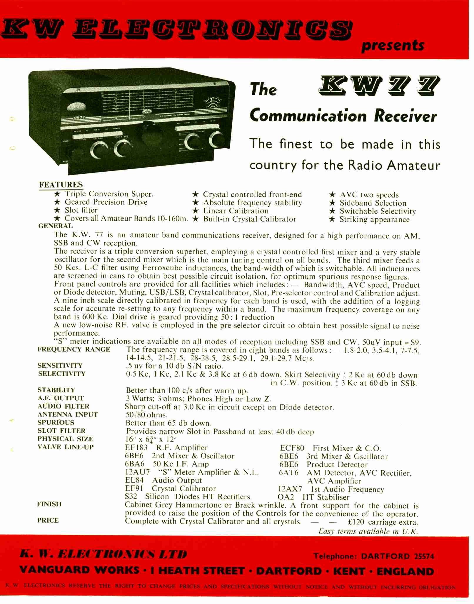
KW-77 receivers April 2018
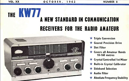
Took delivery of both versions of this receiver within 14 days of each other. The 77 was KWs second stand alone receiver after the very rare KW76 (which bears a striking resemblance to the Drake 1A). There was mention of a KW55 receiver in a 1959 magazine advert, but it dissappeared soon after - it may have been an early name for the KW76.
The KW77 was introduced in late 1962 and is unusual in that similar to early Drake receivers there are no crystal / mechanical filters for SSB reception. Depending on the band its either double or triple conversion with a 50KHz last IF. The '77 is effectively an 80m receiver with a crystal controlled 1st mixer to convert all the other bands to a 3.5 - 4.0 MHz tunable first IF - so its double conversion on 80m (450kHz and 50kHz).
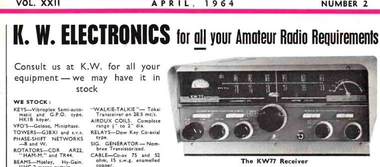
Adjustable selectivity is achieved at 50kHz with a switched LC arrangement using Mullard 'Vinkor' potted inductors which give it a very unique sound on SSB. Opposite sideband suppresion is not brilliant on either of mine on the 2.1kHz setting. As far as I can tell there were a few cosmetic changes and colour schemes over its life and one major circuit revision. Each of mine came with the rare matching speaker. The first is an earlier or 'Mark 1' identified easily by the dial layout and valve lineup. The Mark 2 (from late 1963 to mid 1965) has a different dial and switch layout, a tuning knob with a numbered skirt and a raft of circuit changes. These included different RF input circuitry, modified RF gain control operation and an AGC on/off switch. KW also managed to save a whole valve in the Mark 2 (11 down from 12 !) - using an ECL82 for the audio saved the half a 12AX7 they had used to drive the EL84 in the early version. The initial publicity pamphlet for the 77 is also odd in that it clearly has 10 push buttons in the picture - but all the production models only ever had 8. You have to have your wits about you with this stuff !
The cosmetic differences are clearly visible in the 2 adverts below. The only handbook I can find on the web is for the later version and annoyingly a lot of the components are re-numbered. Not many black front panel models around either - most models appear to be either grey or (later) blue. There are probably fewer Mark 1s around as the production run was short (around a year). I dont think KW ever advertised that the later radio was actually quite a lot different..and not all for the best.
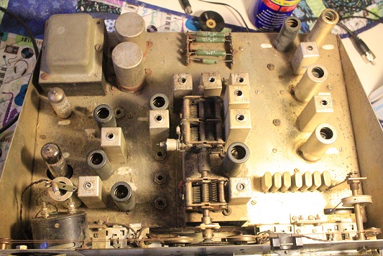
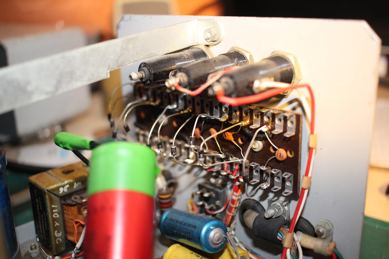
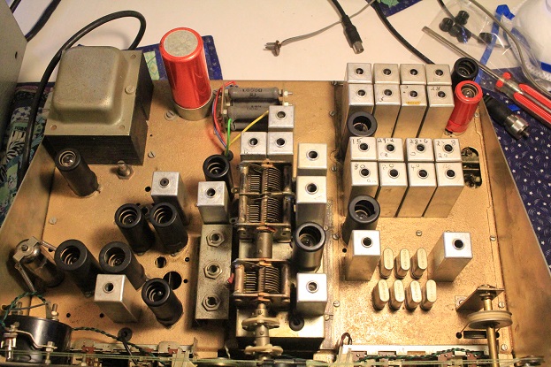 The RF Front end differences are
quite marked - in the Mark 1 / early version there is a proper seperate
slug tuned curcuit (in a can) for each band (including each individual
segment of 10m) on the RF Stage input and
another complete set on its output (thats 16 in total - in nice rows at
the back right of the chassis !). The later model uses a design trait
that KW came up with for the
KW2000 series - whereby the RF tuned cicuits are placed in an incremental
series / parallel arrangment mostly around the bandswitch (most wound straight on
the slugs) and shunt the
80m input coil. There are
actually only 2 proper tuned crcuits with link windings in the front end
of the Mark 2 (T5 and T6) on the in and out of the EF183 RF amplifier. KW even saved a couple more inductors in the 2nd Mixer.
My video
about the radio is here
The RF Front end differences are
quite marked - in the Mark 1 / early version there is a proper seperate
slug tuned curcuit (in a can) for each band (including each individual
segment of 10m) on the RF Stage input and
another complete set on its output (thats 16 in total - in nice rows at
the back right of the chassis !). The later model uses a design trait
that KW came up with for the
KW2000 series - whereby the RF tuned cicuits are placed in an incremental
series / parallel arrangment mostly around the bandswitch (most wound straight on
the slugs) and shunt the
80m input coil. There are
actually only 2 proper tuned crcuits with link windings in the front end
of the Mark 2 (T5 and T6) on the in and out of the EF183 RF amplifier. KW even saved a couple more inductors in the 2nd Mixer.
My video
about the radio is here
All this means there are actually far fewer inductors in the later model - and in my opinion the early one is a better engineered receiver. There was probably a desire by KW management to save costs on the 77 - the second production run was certainly longer. I would be nice to see a handbook for the early version but even the folks on the KW user group have never seen one..........
EARLY VERSION LATE 1962 - 1963 LATER VERSION LATE 1963 - 1965
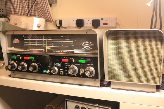
I immediately noted that the cosmetic appearance was rather odd, someone had clearly been drilling holes in the front panel and changed the knobs and buttons. On further isnpection I discovered that the concentric RF/AF gain was now just AF gain and a new RF gain pot had been added to the right of the tuning knob..the on/off switch which would have been on that control was now a separate toggle switch in another new hole...and whats the green light all about?..another bloody hole in the front.
Clearly the concentric control had failed in the distant past. All the small KW knobs have been changed to a more modern skirted type and the Eddystone main tuning knob is gone. Even more strange are the garish multi coloured push buttons..these should all be white. It appears the buttons had cracked and been repainted to hide the marks, but why paint them in different colours?. Its near impossible to restore this radio cosmetically as the parts could probably only come from a donor radio.
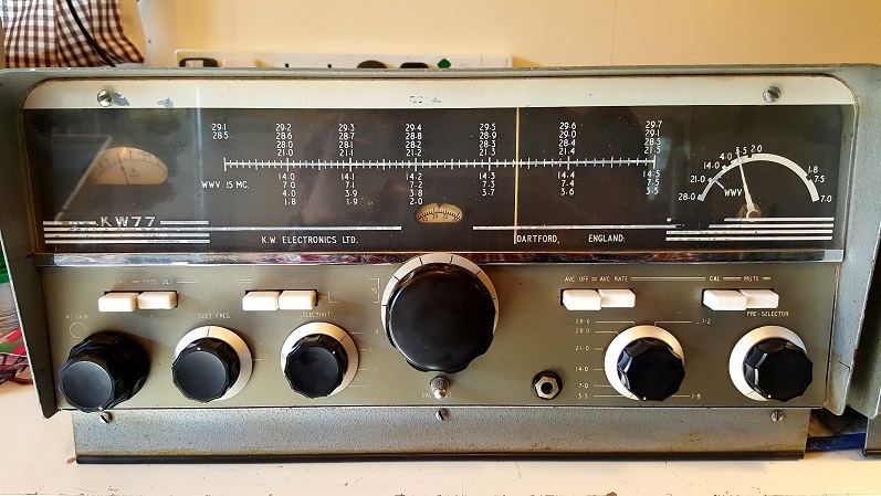
Electrically it came to life straight away with a few easy to find faults. The 50KHz BFO / CIO was way off frequency making SSB sound very thin - a quick twiddle of the appropriate pot core inductor and it was fixed (why was it so far out?). The BFO runs at a fixed frequency with USB/LSB switching taking place by moving the oscillator of the 450KHz mixer stage up or down (it runs at either 400 or 500KHz) before the 50KHz IF...very odd. I changed quite a few nasty HUNTS capacitors (including the PSU ones) and at least 10 resistors.
Apart from the first mixer crystal oscillator, the 2nd mixer (VFO), 3rd mixer and Product Detector all use free running LC oscillators..this makes it absolutely essential to have accurate test gear to get them spot on. I used a scope with a frequency counter function and an accurate generator for 450 and 50KHz alignment - both of my 77s had coils that had been 'twiddled' so far out it had stopped them working properly.
A hum on AM was traced to a slight heater cathode leak - After just a few hours on the bench the receiver sounds great.
KW77 Mark 2
After the intensive 2 weeks of researching and refurbishing the Mark 1 I was itching to get hold of the later version but had not expected to see one for sale. Out of the blue one of my local ham friends offered me his unloved, battered (and probably dead) Mark 2 KW77 for nothing. Untouched for years and owned by a smoker it looked in a sorry state - he was sure the old owner had transmitted into it and burnt out the 'RF input coil'..I knew that there was only one RF input link winding in this radio..and it wasnt burnt out.
The cleaning took took a while - all the knobs were caked in tar and had to be scrubbed. The front panel cleaned up OK but some lettering had worn away. The dial has fared the worst, some of the white lettering has either faded of peeled away - it looks like the tar had reacted with the paint (my Mark 1 is much better).
The pic above is after extensive cleaning
and it looks
acceptable (just). There were no obvious electrical issues so I went
ahead and brought it up gradually. Nice hiss but no signals. The digital oscilloscope was
my saviour and after a few minutes I identified that the 3rd mixer
Oscillator was WAY off frequency. It
 should be either 400kHz or 500kHz
to mix USB or LSB down to 50kHz - it was actually 700kHz. Twiddled L16 and that
brought in signals sounding great (why did Mr Bodger twiddle it?) Now I can follow the manual to align
this radio properly !!!
should be either 400kHz or 500kHz
to mix USB or LSB down to 50kHz - it was actually 700kHz. Twiddled L16 and that
brought in signals sounding great (why did Mr Bodger twiddle it?) Now I can follow the manual to align
this radio properly !!!
The more basic front end of this receiver is just not as easy to set up as the Mark 1 - thats where the main cost saving shows. After 2 days I changed most of the black Hunts caps and a lot of resistors - I did the realignment from the correct manual using an accurate sig gen - at some point I will sweep the last IF to see the actual shape of the 50kHz passband at each selectivity setting. Its pretty good on 160, 80, 40 and 20m. The cigarette tar has really taken a toll on this radio - I reckon it passive smoked for decades !
The schematic on the web for this later version is quite poor quality (probably why it was thought by some to be from the older version), and even then does not precisely match this radio. On the circuit the 12AU7 S meter amplifier is shown half unused..in mine the other half is wired as an yet another audio preamp to the ECL82. There is a also a weird grid bias arrangement for the ECL82 on the circuit (and no cathode resistor in the pentode section)..not present on mine, its wired with a conventional cathode bias resistor. All this makes fault finding very frustrating indeed - maybe thats why I love them so much.
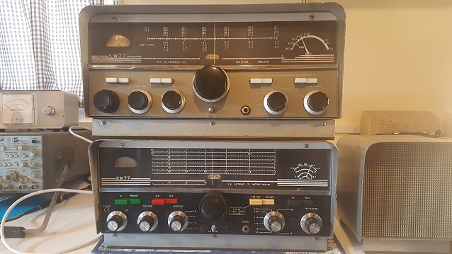
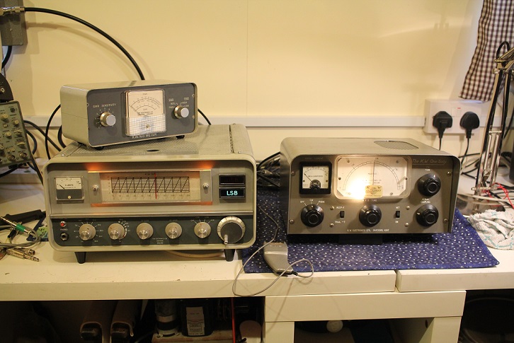
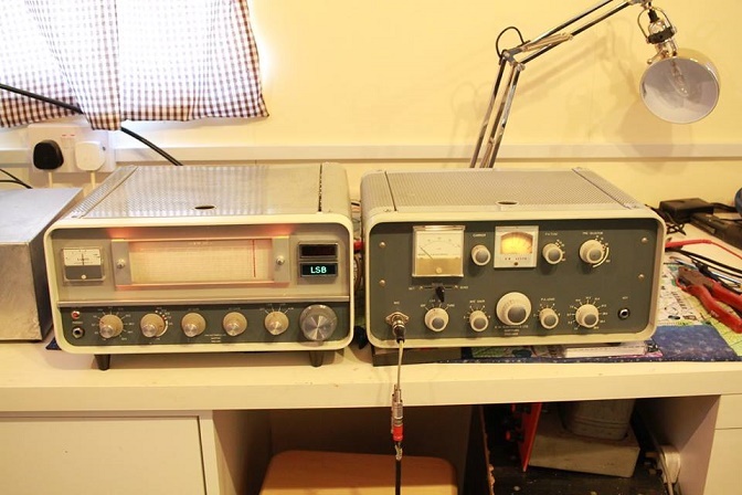
Heres a pic of both the radios together...
KW Viceroy Mark IV - March 2018
This TX came to me through a Silent Key sale - and although I vowed not to restore any of the larger 'boat anchor' radios - I could not turn this down. Its owner had dry stored it many years ago when he moved on to the smaller KW 'G line' equipment. It looks as if its been in a time machine - clean hardly describes this 55 year old TX. I also took a pristine KW600 linear from the same seller
The Viceroy went through a number of variants after the Mark 1 was advertised in late 1959 (initially just called 'SSB Transmitter') and it was still advertised in early 1966 alongside the far smaller KW Vespa TX and KW2000A. Although the Vespa was a more modern design the old Viceroy must have still been selling...the Vespa was cheaper for a reason.
 There were 4 or 5 versions, although some of the info on
the web is confusing (the manual for mine says its a Mark IV - but
there was also a Mark IIIa). There is plenty of room in both the TX and its Power
Supply. I reckon its a
least 4 time the volume of a Drake T4X - they certainly did make them
differently back then. Despite the size of the TX the PSU cannot be fitted inside
the transmitter
There were 4 or 5 versions, although some of the info on
the web is confusing (the manual for mine says its a Mark IV - but
there was also a Mark IIIa). There is plenty of room in both the TX and its Power
Supply. I reckon its a
least 4 time the volume of a Drake T4X - they certainly did make them
differently back then. Despite the size of the TX the PSU cannot be fitted inside
the transmitter
The PSU had a leaking HUNTS capacitor on the neg bias rail and a couple of obvious dry joints. The main unit has a lot of tarnishing to the large Post Office style open frame relay and the 18 way power connector on the rear panel. A few nasty black Hunts capacitors and out of spec resistors to change and then some extensive cleaning....More to follow...................

UPDATE - I couldn't find any adverts with pictures of the Mark IV, the Viceroy IIIa pic below is from a 1963 advert and that states the PSU is internal - by all accounts a very heavy beast !
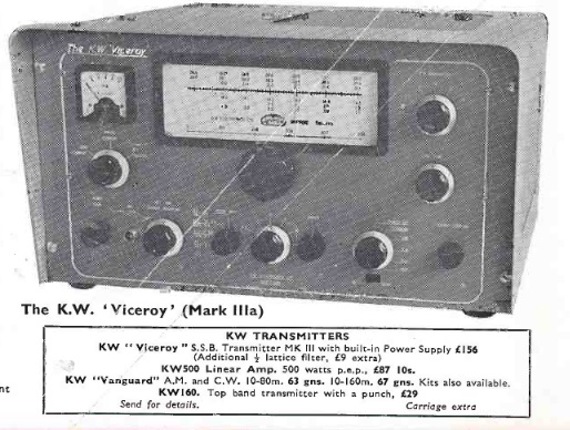
 The
Viceroy suffix changed in mid 1964 to the Mark IV (advert on right). One
of the main improvements in the IV was an extra set of relay contacts to
switch the antenna through to a receiver. Although the ad clearly says
the Mark IV has an internal PSU, my Mark IV can't have an internal PSU
fitted into in its case - its too small. After a bit of research it
seems KW had an option to put the TX into a shallower case and have the
PSU outside - this makes the whole thing a lot easier to move!.
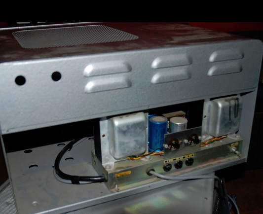
This picture is off the PSU chassis fitted inside the larger case of a Viceroy. My PSU is
identical but fitted into a very nice separate little box - which is
clearly a production item.
The
Viceroy suffix changed in mid 1964 to the Mark IV (advert on right). One
of the main improvements in the IV was an extra set of relay contacts to
switch the antenna through to a receiver. Although the ad clearly says
the Mark IV has an internal PSU, my Mark IV can't have an internal PSU
fitted into in its case - its too small. After a bit of research it
seems KW had an option to put the TX into a shallower case and have the
PSU outside - this makes the whole thing a lot easier to move!.
This picture is off the PSU chassis fitted inside the larger case of a Viceroy. My PSU is
identical but fitted into a very nice separate little box - which is
clearly a production item.
Earlier models - The Mark 1 Viceroy had a valve PSU nearly as large as the TX itself (I owned one in 1971). It only had USB on 40m and as I recall there was a mod with an extra valve or two to mix 40 down to LSB on 160m - that got me onto topband SSB !
The Mark 2 had 40m LSB and a smaller external PSU in a narrow case - there were some controls on the PSU.
The Mark III moved all controls onto the transmitter and the PSU was internal. I dont know if an external PSU option was offered. Although there are adverts for the IIIa in 1962 I dont know what the differences are.
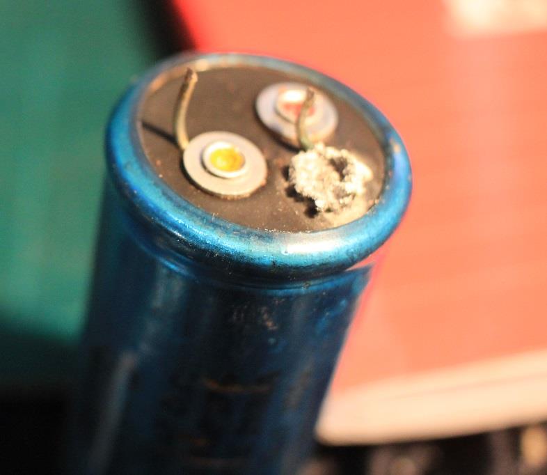
So it looks like mine is from 1964/5. My initial test of the PSU was eventful - although I had changed the leaking neg bias smoothing caps I should have also spotted that the first resorvoir capacitor on the 250V line was near death...and despite a slow start up it quickly heated up!..as its a dual 32 +32uf component I replaced it with 2 modern high quality ones. On initial test the radio works great on 80m with 100W out and reports of super audio with an ACOS crystal microphone plugged into the Belling Lee coax connector (so loved of UK ham radio manufacturers in the 60s)
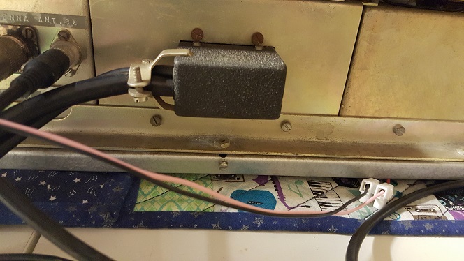
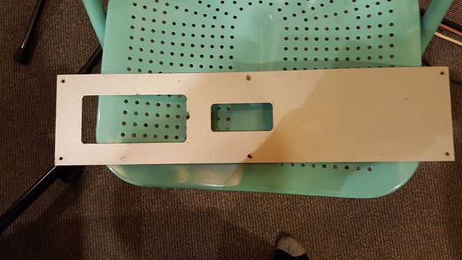
My radio has a large metal plate across the lower rear of the case..although this fits the case perfectly its impossible to get the 18 way power connector plugged in with it in place. This had me stumped for a while until I found a KW Viceroy 'Exciter' described here - the Viceroy 'Exciter' is in the same shallow case as mine...but as there is no PA in the exciter a PSU is fitted inside - this has the same blanking plate but of course it doesn't have the a big power connector on the back. This explains the option to have the Mark IV Viceroy in n smaller case - a case that KW already had on the shelf for the 'Exciter'. Amazed that on mine the plate and all its screws have been kept..the late owner must have put the plate back on when he stored the radio over 50 years ago.
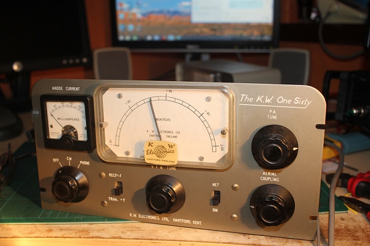
KW 'One Sixty' TOPBAND AM TX - November 2017
Been after one of these for a few years. This came from an ex KW employee who decided to sell. Although it worked I quickly decided to replace all those nasty Hunts capacitors. Very little documentation although there is an article on the Web..the schematic around the VFO does not match my one though. Uses a TV PL81 valve in the PA with 21V heater winding on the mains transformer..Rowley must have got them cheap as it would have been more normal to use a 5763 or 6BW6. Power supply built in and full ' plate and screen modulation' from a 'push pull' audio stage. Its unclear when the 160 went out of production, it certainly ran alongside the KW2000s up until the mid 60s - although its look is distincly 1950s !.
As we moved into the mid 60s the smaller, lighter and cheaper Codar AT5 became the Topband AM transmitter of choice for most UK hams - and has now achieved cult status !. I was one of many that copied the AT5 design, its 'choke' modulation did away with the need for a heavy and expensive modulation transformer..and with no bulky PSU built in, it was perfectly suited to mobile and portable operation.
G3ZPS 160m AM Station for GB8KW January 2018 - KW 62nd Anniversary
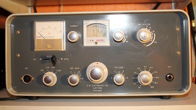
KW VESPA MK1
Ebay purchase delivered in Jan 2016 - KW Vespa Transmitter (MK1) and its obviously re-built power supply, oh dear, what a mess. No way was I turning it on in this state - even more dangerous than when it came out of the factory in its odd cardboard cover, re build required. I changed caps, fixed awful dry joints, corroded fuse holders and put decent HV diodes in for the 750v HT..the ones in there did not look all that great.
After a 2 day total rebuild and test, the PSU was in good working order. Firing up the radio was met with ZERO output..not a milliwatt. Out with the scope and it soon became clear that the dreaded 455KHz Kokusai mechanical filter was as dead as a dodo, 455KHz carrier went in and nothing came out on the scope As a quick and dirty check I bypassed the filter with 1000pf...Bingo !!! Double Sideband and loads of drive. In the box of bits that came with my purchase there was 2 other filters one opened and one sealed.
On a whim I put the sealed one in the VESPA and it came to life again...super reports on 40m with a Shure 444. Later I found some resistors had gone high, and the curse of the KW Owners manual caught me out several times. Its one area where they really cut corners - the manuals are awful, child like drawings, schematics and charts with errors. Compare them to Swan, Drake and Collins and you will see what I mean.
FEBRUARY 2016
Very clean KW201 Receiver from the 2016 Canvey Rally (Essex UK). Cheaper than eBay and promised as working on AM and with a good Mechanical Filter - but not good on SSB. This was a quick fault find quickly traced to an almost shorted coupling cap from the anode of the product detector to the grid of the Audio O/P valve.
That's why it worked on AM but not SSB. This receiver has a 3KHz filter which is too narrow for AM but means that SSB sounds great provided there are no adjacent stations - of course you can add the optional Q Multiplier - but I have never seen one for sale BEWARE the old carbon composition resistors in these KW gear, in the KW201 2 failed within a few days of getting it going, they all go high, but some just go VERY high.. Although the 201 came out at the same time as the VESPA transmitter they cannot 'transceive' together and have to be manually netted together - this an another odd KW design decision, even the later KW202 and 204 'separates' had to be netted onto the same frequency and they were in production into the mid 70s. Drake separates all allowed proper transceive operation.
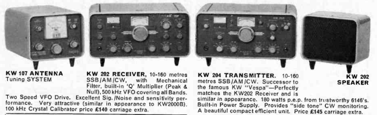
The KW202 receiver is almost identical to the KW201 although it looks more like a KW2000B. The company re-used the same PCB for the 202 but had to add extra gangs to the VFO capacitor to account for 500KHz band segments, the Q multiplier was standard on the 202, but took up the space where the speaker was in the 201. And it gained that weird front end RF atteuuator (as in the KW2000E) which was called RF gain !. The IF gain on the 202 is the exact same control that was marked RF gain on the 201...!!!!
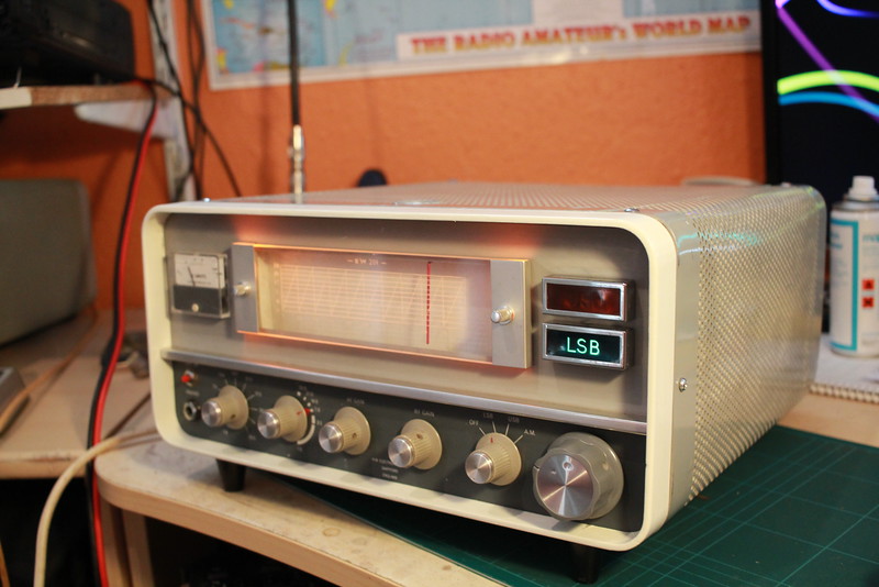
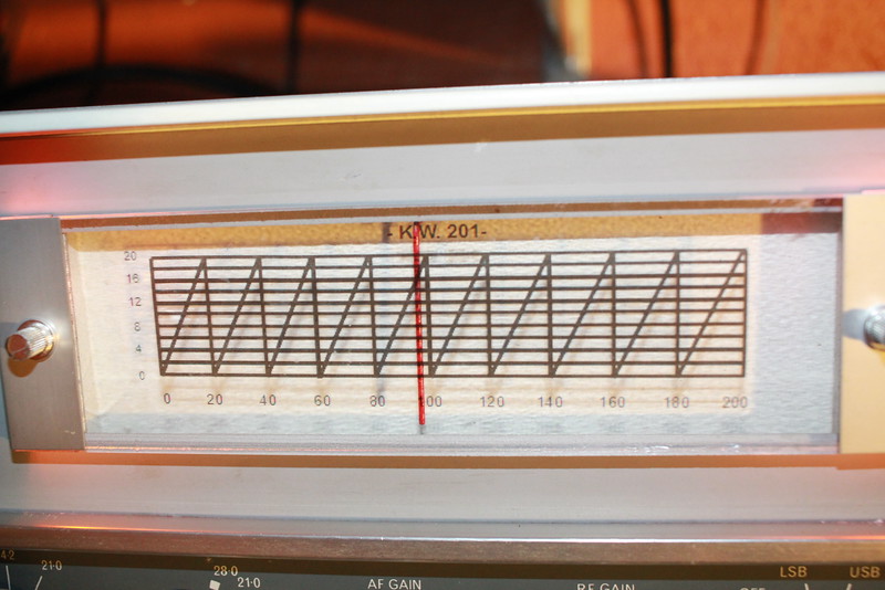
Below - Feb 2016, made a new slide rule dial for the KW201, using new perspex (cut to size and delivered off the internet) and an inkjet printed waterslide transfer. Took a bit of work in MS Draw to get the graphic the right size and looking good. But black is far better than the white lettering of the original. Its a strange dial anyway - good idea, but impossble to get better than 2KHz resolution (if your lucky and have good eyesight). I guess that was deemed good enough in 1967 - some stations I work now tell me my frequency to 5 decimal places !
The white lettering of the 201 dial on mine had faded and past efforts at clenaing it had only made things worse. I decided to buy a pre-cut blank piece of perspex and remake the dial in black. I used MSDraw and created a new one from scratch - I then printed it onto a waterslide transfer and applied it to the back of the perspex..looks ok and easier to read.
The Vespa and KW 201 are really only the TX and RX parts of the KW2000 transceivers and had similar limitations - only one filter bandwidth meant poor AM and CW performance, 200KHz band segments meant part coverage of 15 and 10m and did I say no transceive !
Connect with me today
Call me on 44 (0)7970 190437