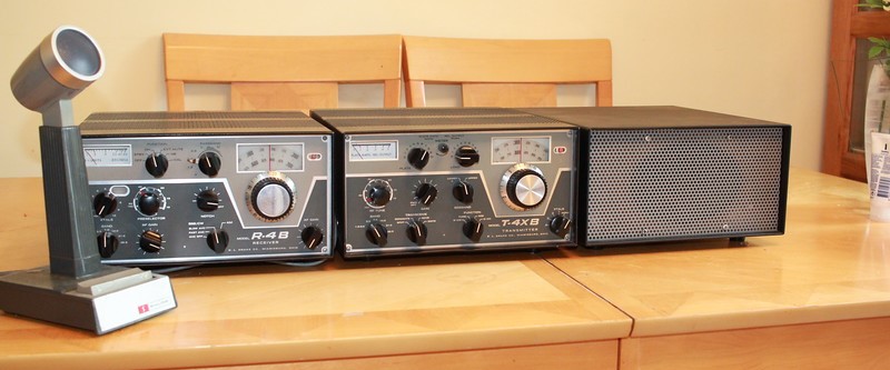
SWAN, Kenwood, Alda,QRP, microphones, CODAR AT5, BITX 40, Ten Tec, Eddystone, WWII Paraset and The 'Sphinx Transmitter'
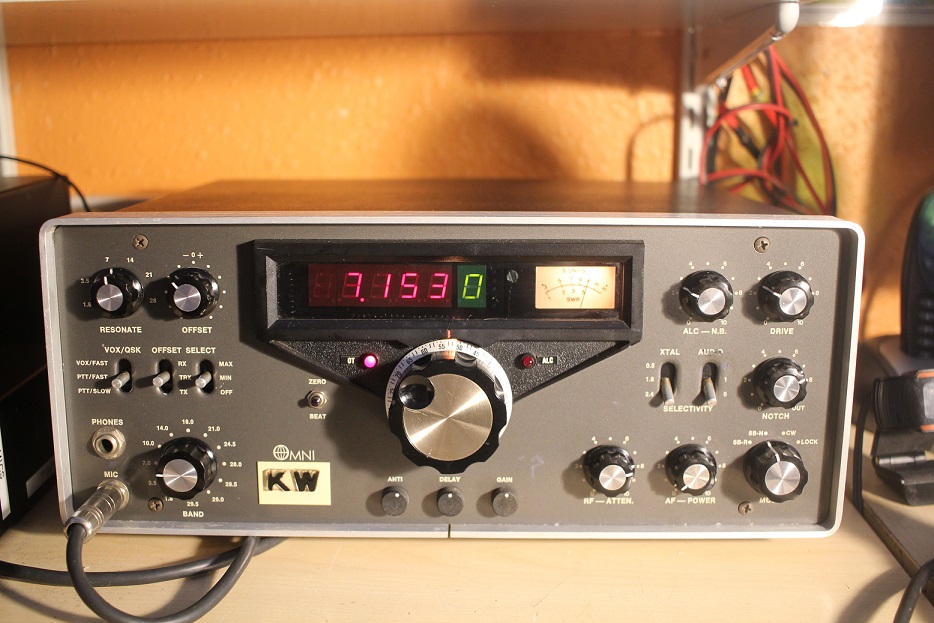
March 2022 Ten Tec Omni D
This radio came from a local hamfest/rally (the first local one in 2 years). I walked past this radio quite a few time before chatting to the seller. It was imported from the USA and re-badged by KW Electronics after they stopped making their own equipment – this one probably dates from 1982. The rather horrible plastic 'KW' logo looks awful and it would have looked far better with the actual makers logo. The knobs are non-original but look pretty close. These OMNI models numbers around this time can be confusing, especially when the WARC bands came along !, this one is badged as an OMNI D version C - serial number 546-4229
The seller did not want to take the radio home and even had a test sheet with the OP power on every band. After wavering and with some cajoling from a close ham friend I bought the radio for a good price
Ten-Tec are new to me so this was a voyage of discovery !. The seller was open about mods made to the radio and the first was a rewired power connector which was now on 2 flying leads coming out of the radio. Once connected the radio came up and I was able to have contacts on 40m with reports of very thin audio. The RX audio was also very harsh and reverse SSB or 'SB-R' was so far out the carrier oscillator must be a long way of. Reverse SSB is not really needed most of the time as the mixing scheme selects the right sideband on each ham band
The documentation is good, although the schematics look a bit hand drawn and there are some inconsistencies with the actual radio. The construction is odd with each individual board screwed to the chassis – not all the boards have screen printing on them although the manual identifies everything so its easy to work on, even if it looks partly home made !
Adjusting the carrier oscillator was quick and easy using the manual and the audio came back to normal – it was a long way out. After the carrier osc is correct as per the manual the reference oscillator in the counter can be tweaked to get the display correct, but with only 100Hz resolution its a compromise. It took me an hour or two but I have got it very close.. An odd LED was fitted in place of the S meter bulb – it failed in 2 days so I replaced it with the correct #47 bulb, sometimes old tech is best.
Another oddity is that the push/pull on off switch on the AF Gain is not connected to the 12V input. It can be used to switch the mains for an external 12V PSU as there are (or were in this case) 4 pins on the connector ; 2 for tthe 12V input and 2 isolated pins from the switch. Ten-Tec explain in the manual that the switch would not stand up to the up to the 18A that could be drawn on full power transmit. Weird but thats the way it is !
The linear switching socket did not work and the seller told me a link had been cut by a previous owner to stop the relay noise in QSK CW. He was right ! - a leg was snipped on the transistor that drives the relay. The odd push pull switch for the attenuator caught me out as well - Its impossible to tell which position its in. Although the attenuator only switches DC (to drive a PIN diode switch), it has become intermittent and will need further investigation. The manual unhelpfully does not show the position of the PIN diode attentuator board
The biggest issue with the radio is the lumpy PTO, that also 'warbles' until it settles. I have not attempted the major surgery to strip down the radio and renovate the PTO, its quite daunting. I also don't know if some of the parts are so worn that it wouldn't be any better at the end of the work. The seller has offered me a spare counter chip and the correct lithium grease for the PTO lubrication, it is however stable once set.
There were a few light scratches on the front panel and paint loss around one of the filter switches. Its always hard touching up a front panel as the paint colour is normally unknown. I struck lucky here as the colour looked like 'gunmetal' and on a whim I bought a small modellers paint tin which was a perfect match
The Noise Blanker is also rather confusing, it does nothing to the many 'woodpecker' souding radars which now plague the HF bands, but oddly works quite well on very'spiky' crackly noises.
The audio on receive is very smooth and there is no listening fatigue, CW is also superb with seemless break in. The one relay is not used inside the radio for internal T/R switching. I have already worked round the world on 40m and quite like this radio !. ...that is until something else comes along.
Although Ten-Tec were more of an amateur radio outfit in this period they managed to up the game culminatimg in the stunning RX340 receiver sold to the US Govnmt at a price that undercut the competition. It was probably the pinaccle of their achievement before the rot set in and the company ended up being sold 3 times in as many years around 2015. Its current state appears unknown.
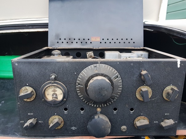
National NC101X receiver (1937/38)
This was another entirely unexpected find !. During August 2021 my radio club was contacted by a local house clearer who had found some 'old radios' in one of the rooms and had a vague idea that someone may be interested. If not they were heading for landfill. We determined that the late owner was a member of our club over 50 years ago and we would pop round.
 We
found and removed 2 very old receivers and some small items which we
offered to club members for a donation to the estate. The receivers were
a National NC101X and Hallicrafters BC342, the 1937/8 National was of
interest to me as it was made alongside the very well known HRO. The HRO
is quite common in the UK as many were used in WWII listening stations
and over the years have found their way into the shacks of vintage radio
enthusiasts.
We
found and removed 2 very old receivers and some small items which we
offered to club members for a donation to the estate. The receivers were
a National NC101X and Hallicrafters BC342, the 1937/8 National was of
interest to me as it was made alongside the very well known HRO. The HRO
is quite common in the UK as many were used in WWII listening stations
and over the years have found their way into the shacks of vintage radio
enthusiasts.
This is what it looked like before cleaning
During the 1930s the National design team developed an aversion to any form of bandswitching in their SW receivers, feeling that long wires to a switch would reduce performance and create dead spots across the short wave spectrum. It was a challenge, but for the HRO they came up with a plug-in coil solution that completely eliminated these problems. They also designed a very unique dial and drive assembly called the 'micrometer'. Nothing quite like it was around in the mid 30s – if you had some of the ham band coils you could easily reset the frequency to within 1kHz
Although the HRO was a big success, amateurs had to buy a 'bandspread coil pack' for each band and then find somewhere to store them. Back then there was no 15m band so 5 coil packs were needed for 160,80,40,20 and 10. If you wanted any general coverage capability that was even more to buy !
National realised that there could be a big market for lower cost receivers that did not need a whole bank of separate coils. Again they wanted band-switching that did not require rotary switches and long leads. This time the solution was to have a large coil pack inside the radio that was moved to connect directly with the valves above it. Its a heavyweight bit of engineering, the coil pack is in a box a bit smaller than an A4 page, fully screened and with 3 coils and trimmers for each of the 5 ham bands. The whole assembly is on runners that allow it to move across the underside of the receiver, a rack and pinion gear drive moves it left and right. The coils connect through pins and big spring clips...'clunk clunk' as you turn the band change knob !
National brought out a range of general coverage and ham band only receivers using this concept and the NC101X is the ham band only version from the late 30s. It came with is companion loudspeaker, which has the OP transformer inside. The speaker is 10 inches and handles the 7W push-pull valve output stage for a BIG sound.
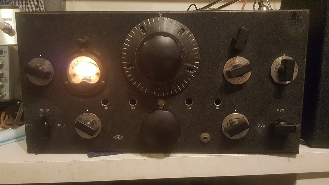
After downloading the manual (the USA collectors have excellent records) I set about cleaning the beast and assessing its general condition. I quickly saw the it had some mods that must have been done as far back as the 50s, the replaced PSU capacitors were dated 1948 and did not fit properly. Also added was a neon HT voltage stabiliser tube for the VFO - that also dates from the 40s/50s. There was nothing for it but to remove the old PSU caps and replace them with modern ones. I also added a 3 core mains cable with a USA style plug – and a friend lent me a 115V step-down transformer. More checking confirmed there were no shorts on the HT and it was time to see what would happen at switch on. Apart from a faulty RF gain pot that needed cleaning it came up straight away !. I was stunned, on both SSB and AM it sounds amazing, the single crystal filter makes CW sound really good. Look at my youtube video here
 Having
confirmed I had a working radio I set about replacing the old wax/paper
capacitors in the main part of the receiver – after all they are 83
years old !. In fact only one fault remains – a weird internal toggle
switch that disables the AVC is open in both positions, the AVC is on
all the time..not an issue. I have had some communication with USA hams
who have these in their collection, but not I suspect many in the UK.
How it got here all those years ago is anyone's guess, but its been
saved from the dump and now sits happily in my workshop !
Having
confirmed I had a working radio I set about replacing the old wax/paper
capacitors in the main part of the receiver – after all they are 83
years old !. In fact only one fault remains – a weird internal toggle
switch that disables the AVC is open in both positions, the AVC is on
all the time..not an issue. I have had some communication with USA hams
who have these in their collection, but not I suspect many in the UK.
How it got here all those years ago is anyone's guess, but its been
saved from the dump and now sits happily in my workshop !
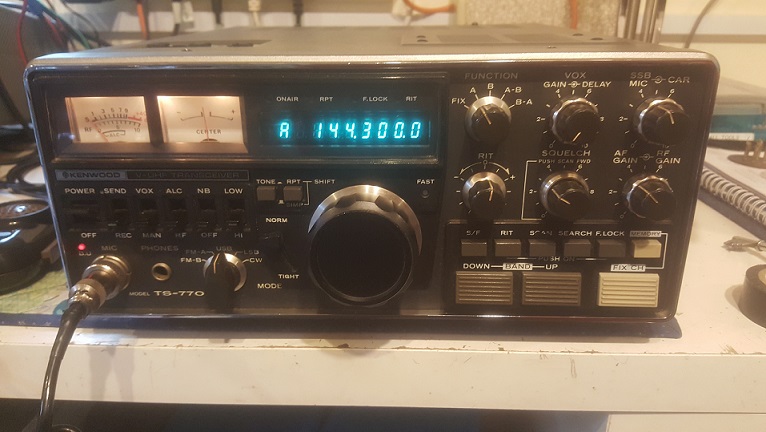
Kenwood TS770 - September 2020
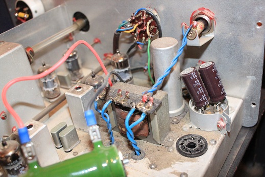
This early 80s VHF/ UHF base station came to me from a close friend who was not a Kenwood fan and warned me that horrors awaited inside the case. Yet again it had been subjected to some serious bodges and mods by a previous owner - by far the worst was the appalling fit of a new mains transformer, you just have to look at the picture to see what he had done. My friend had tested out the radio and found it worked most of the time, however after about 2 hours it began to play up as the Phase Locked Loop synthesizer started to randomly lose lock. Despite a PLL alignment the fault persisted and he passed the radio on to me.
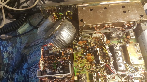
My further asssement revealed a number of other mods that were probably made to allow packet radio operation and I set about tidying these up. Along the way a rear panel switch had been removed but kept rattling around inside a small plastic bag, the original accessory socket was also just left inside the radio. I pondered whether to remove the mains transformer and have the radio run from a DC supply only, but in the end after tidyng up the PSU wiring I decided to leave it where it was !.
The next task was to locate the PLL unlock issue and this proved to be more annoying. In hindsight the symptoms should have lead me to the solution quicker but as it took at least 2 hours to occur (and sometimes just clear) it was not a quick fix
The problem was far worse on FM although SSB remained usable. I could see the PLL output stuttering but could not understand why a mode change would affect it. Freezer spray around the PLL and VCO components had no effect at all, and the service manual was not that helpful - frustrated, I left it for a few days.
When I came back to the radio I was determined to sort it. Up until this point I had ignored the small carrier board tucked away with the USB/LSB crystals as the main block diagram showed no link with them ...WRONG !. As the freezer spray touched the crystals the fault immediately cleared and the PLL OP was restored on FM. This was the key - the carrier crystals are used as part of the reference for the PLL For FM the frequency has to be a slightly different to SSB so the display reads correctly. Rather than fit a 3rd crystal Kenwood sneakily just used a diode switching arrangement to add a padder trimmer across the USB cystal. This was the root of the problem - the crystal had drifted with age and now the extra padder trimmer was too much and it would stop oscillating once warm - only affecting FM. I tweaked the padder capacitor to pull the frequency back to the figure buried in the service manual and the radio works fine...bliss
The TS770 is a complex radio, made in the days before surface mount and DDS frequency control, its crammed with thru-hole components and I am amazed that this example has survived for nearly 40 years despite the mains transformer failure and the attention of a yet another ham who should not have been let near a toolbox. It was Kenwoods first V/U radio and attempt at a satellite capable base station - and does not appear to have sold in very large numbers. There is not much info on the web..although the later TS790 is very highly regarded. Only 10W out on either 2m or 70cm so an amplifier is/was probably a good addition.
QCX QRP - August 2020
I bought the QCX CW transceiver kit direct from Hans Summers of QRP-LABS in Friedrichshafen when I was there in 2019. The COVID lockdown gave me the time to build this brilliant little kit - its the 40m version. Hans redesigned the PCB in mid 2020 so newer versions have a bit more room and will fit into a better case.
Hans is a very good engineer and the QCX is nothing short of a masterpiece of RF design. The receiver uses an unusual architecture based around the 'Tayloe' design. The older kit has quite a dense PCB although both the DDS and the multiplexer SMD chips are already mounted - in total there are around 280 solder joints to make, a small iron and a steady hand are required !.
There is only one challenging component - the front end toroid - the performance of the receiver rests on this being correctly wound and soldered in place. Windings on the core are a tight fit on 40m but the instructions are very good - in fact the whole manual is a superb document that is on a par if not better than the Heathkit manuals of old
Mine went together without a hitch and worked perfectly at switch on, there are built in alignment tools that make setting up a doddle. The on air performance is nothing short of staggering - the RX is a super perfomer. It hears down into the noise and the narrow 200Hz filtering (one sideband is also suppresed) is just right. ARRL tests have shown some amazing figures for the receiver. Its close in RMDR (at 2kHz) is around 71dB..and whilst not in the league of the big guns still compares with many of the older rigs like all the FT1000s, FTDX1200 and many others. The DDS goes down to 10Hz resolution and coupled with a keyer, CW decoder and memory options there is nothing missing.
Adding a case to this older style QCX costs more (although a 3D printed one would be great) and its single band. Despite this its hard to justify spending many £100s on some of the other CW QRP radio kits, especially ones with a standard direct conversion RX with an old syle VFO
I get a solid 4W out and have found that most stronger stations come back within a couple of calls and my best DX to date is 1000mls running into a 40m dipole.
Alda 103 - August 2020
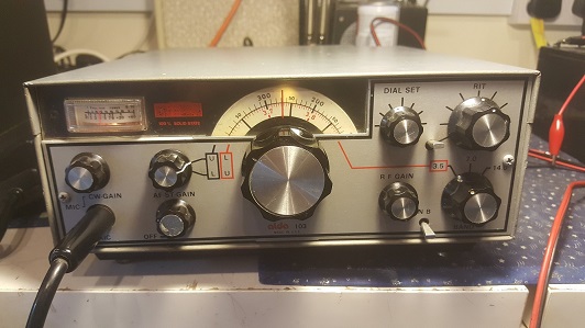
This very unusual late 70s radio came to me through the SK sale of a very old friend -this radio was buried at the back of his workshop. I knew about these ALDAs from my extensive research of rare 70s ham radio gear but had never expected to either see one in the UK or have the option to get hold of one. I made a contribution to the estate and started to look over the small and very light little USA built 100W transceiver, most of the manual and service information was quickly found on the web pages of Anthony K4VIZ
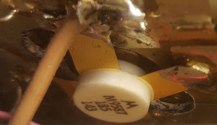
It was only a few minutes before I found the key issue with this example - at some point in the distant past the MRF454 finals (and driver transistor) had been replaced by much smaller VHF devices. This means its now a 'near QRP' radio that will only generate 10 - 12W key down. It would be quite an expensive job to rebuild the PA with the original transistors - they are not cheap (unless you buy dodgy fake ones!). Many of the other components and matching trasnformers have also been changed.
There are of course options for other devices and FETs, but I have to balance that against the value of the rig and the work required - so for now its a nice little 3 band (80,40,20) 10W PEP radio.
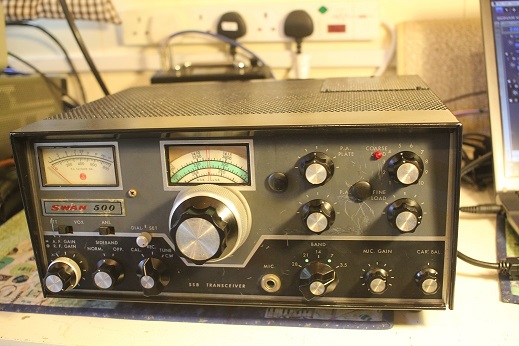
SWAN 500 July 2018
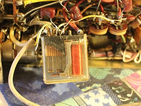
This radio (1967 model without PSU) was given to me by a local ham friend..it was an unexpected gift..and he must remain nameless. To say the radio was poor is an understatement. Although it was complete, there were several undocumented mods (including IRT), holes drilled in the front panel, holes in the case and a weird relay mod hanging out the bottom. It was very very scruffy and the mode switch had been rewired. The internal speaker was full of holes and the PA cover was missing. It was so bad I left it for several days before finally deciding to clean it up and remove the bodges..the soldering was the worst I have ever seen
After 2 days dismantling and cleaning it was time to test the RX. I removed the 6HF5 PA vales and just ran it up on heaters, HT and -bias. After more relay cleaning the receiver came up and appeared to be OK. I could not test the TX until the mode switch was rewired as the TUNE position moves one of the carrier crystals into the filter passband. The tracing of undocumented wire colours and their correct position on the wafers took another day
The KW Atlanta (I own a superb example) is pretty much a component level copy of the SWAN 500C (although there are some minor differences). KW also saw fit to swap 2 wires on the 12 pin Jones power plug compared to SWAN. This meant I had to make up an adaptor to fully test the SWAN without changing the KW PSU.
I moved carefully - testing the RX first, then the relays, finally checking I had good SSB up to the TX Driver stage. Next it was time to reinsert the PA tubes and bring the TX up slowly. I was amazed to see good power come up in tune mode..well over 100W on 80, 40 and 20m. Contacts quickly followed and after tweaking the carrier crystals the audio reports were super.
Cosmetically there is little I can for the front panel - I filled the bigger holes with plastic blanking plugs and painted out the worst gouges. Next I made a plate to cover the big hole in the case above the PA. This meant cutting a square plate of perforated steal and placing it over the hole. The case repaint (black Hammerite) made the repair look acceptable. I found a new ellipitical speaker of the right size on eBay and added a small 12v fan on the back of the PA compartment.
Yet again I wondered what was in the mind of a bodger that made him think that cutting a huge hole in the case over the PA compartment with a big fan blowing was a good idea. The anodes inside the vaccum of a valve will not be cooled much by blowing on the glass. What is required is to keep the components around the valves cool...that means you just need to extract the hot air from the cabinet and that doesn't need a big fan or a whopping great hole.
The 500 was produced in 1967 with a production run of just under 3000, the updated 500C came out in 1968 with different PA tubes (6LQ6) and some minor changes. There were 7 sub models of the 500C as Swan fiddled with the design well into the 70s. Around 1973 the even higher power Swan 700 came out - this used a pair of the now very rare (and expensive!!) 8950 valves - quite a few US Hams converted the rig back to cheaper TV 'sweep tubes'. The 700 was really just a high power update to the 500C.
Swan were an interesting company - for their tube Ham Radio transceivers of the 60s and 70s they stuck with the 'switched VFO' design that saved a bit of money but meant terrible readout accuracy on the higher bands (10m is every 10kHz). This makes tuning very touchy and drift is an ever present problem. The poor dial resolution on all the bands was an issue where the competitors were ahead. Dial drive arrangementa that achieved 1kHz readout were easy when the VFO operates on just one frequency span and drift is far less of a problem. The Drake TR4C was such an example - but at a higher cost.
Performance on 20/40/80 is very good and unlike KW and Heathkit, Swan used good quality components that have not aged badly. Amazing to report that I have not changed a single resistor in this 51 year old radio. There were some threats of litigation from the Drake Company over the archictecture and look of the transceivers, but that came to nothing
They also stuck with tube transceivers into the late 70s although the SWAN / ASTRO brand name produced some innovative solid state gear from as early as 1973 under the CUBIC ownership of SWAN
Swan founder Herb Johnson left the Company in the early 70s and after a few poor job choices he started the ATLAS Ham radio Company. Atlas produced some great little HF transceivers, but like many US ham radio equipment manufacturers of the time they could not produce a technically reliable product at a price point to compete with Yaesu, Kenwood and Icom. The excellent SWAN RADIO COMPENDIUM is linked here
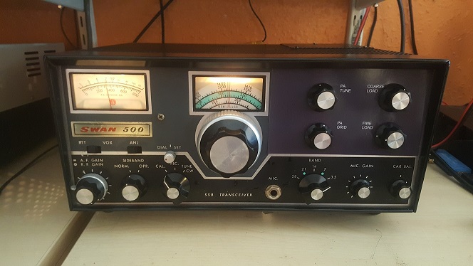
May 2020 update - SWAN 500
During the 2020 'lockdown' I decided to try and give the Swan a bit of a facelift. The biggest problem was the awful holes and scratches around the PA controls (why????). After deliberating on filling the holes and repaint part of the panel I hit on the idea of a photo paper overlay. This has worked quite well although the photo quality print changes the shade of grey slighlty at the print stage - I may redo to get a better colour match. The dial and meter light diffusers were very dirty and I had the front panel off completely to clean them. This meant I could also touch up the scratches with matching black and grey paint. Considering how bad the radio was when I first saw it, the end result is quite acceptable. I think it would have been junk without my care and attention. After a tune up tweak on 80m it delivers over 200W PEP on my calibrated peak hold (well speech peak of the RMS power if you know what I mean !)..sounds great as well Later in may 2020 the receiver developed a fault that made the audio sound like a duck was trapped inside the radio - this had me scratching my head for an hour or 2, it turned out that part of the can decoupling cap (C202) on the HT had failed allowing all manner of noises to permeate around the radio. As a stop gap I snipped the leg off and used a new modern capacitor under the chassis. Its a 3 section cap and will need to be re-stuffed at some point
Microphones
 been buying up mics from radio rallies for many years and
never spent a lot of money. Shure 444 and Shure 201 mics works very well
with all the tube / valves radios, but a recent addition (Dec 2017)
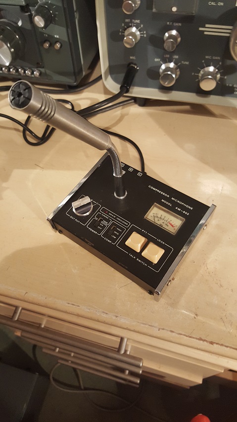
amused me with its quality on my FT902DM. The Adonis AM802 'compressor
microphone' is a strange one - it has 3 separate switched outputs..and a 3
position compression setting along with a 'tune tone' and a small
electret capsule. I was given this before it was thown out and wired one
of the outputs for 4 pin Yaesu - there is no schematic or useful
information anywhere on the net . The results on my 902 are quite simply
amazing, my 80m ragchew chums love it..and my off air SDR recordings in
the UK sound great. The response is very flat and it appears to suit
both my voice and the radio . I cant imagine needing any
improvement to the clear comms quality I get with this mic - I'll tell
everyone its a Heil
been buying up mics from radio rallies for many years and
never spent a lot of money. Shure 444 and Shure 201 mics works very well
with all the tube / valves radios, but a recent addition (Dec 2017)
amused me with its quality on my FT902DM. The Adonis AM802 'compressor
microphone' is a strange one - it has 3 separate switched outputs..and a 3
position compression setting along with a 'tune tone' and a small
electret capsule. I was given this before it was thown out and wired one
of the outputs for 4 pin Yaesu - there is no schematic or useful
information anywhere on the net . The results on my 902 are quite simply
amazing, my 80m ragchew chums love it..and my off air SDR recordings in
the UK sound great. The response is very flat and it appears to suit
both my voice and the radio . I cant imagine needing any
improvement to the clear comms quality I get with this mic - I'll tell
everyone its a Heil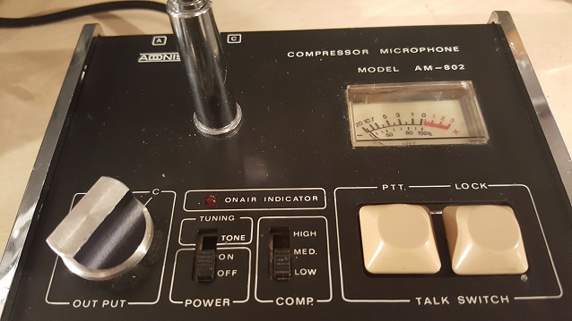 !
!
I am not a fan of extensive audio processing on SSB, A limited amount of EQ and and processing is of course necessary to get the best out of the mode...but taking it to extremes in terms of bandwidth with racks of outboard gear and even adding reverb are not my thing.. I leave that stuff in my music studio.
Eddystone 870A
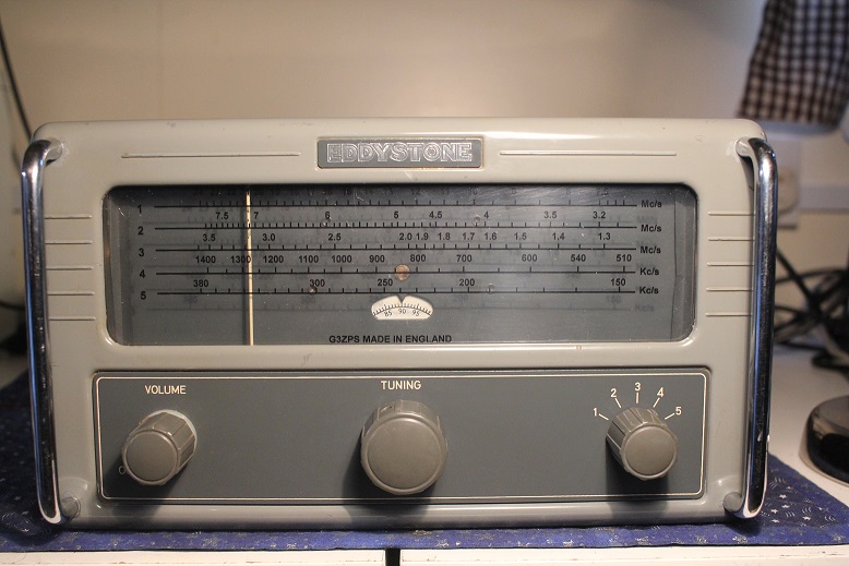
This cute little receiver came from the
'bring and buy' at a local radio rally in November 2017. Eddystone
made the 870(A)from the mid 50s for about 10 years mainly for use in
cruise ship cabins. The design is loosely based on the classic 5 valve AC/DC layout - but with that lovely slide rule dial covering
LW to 24MHz AM. Its extremely well made and above the standard of many
Broadcast sets of the 50s and 60s. The live chassis layout allowed the
radio to operate from cruise ship power supplies as well as domestic
mains..and the chassis is well isolated from the case - I was not
worried about plugging it in!. Some appear in maroon and green -
and have become very sought after, the grey ones are less rare.
It had been electrically checked over by its previous owner and works fine - but he ran out of enthusiasm to replace the cracked dial glass. He cut some perspex to fit and then didn't know what to do about the lettering..so he just scored 5 the lines with a knife....useless.
Once home I threw out his dial and cut out a new blamk perspex dial window. I then made up a replica frequency scale that precisely matches the original in MS Draw. Sadly printing in white is not an option so the frequencies are now printed in black on an acetate sheet behind the perspex. Looks OK and works even better after alignment but boy does it get hot on 240v..that big dropper resistor must be dissipating over 20 watts !
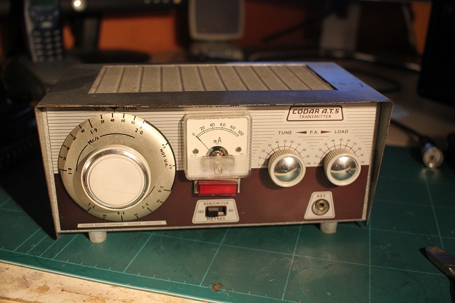
Codar AT5
In the UK back in the 60's 160m mobile became quite popular...it was easier to operate on this band, rather than 2m and local ground wave contacts were quite adequate for staying in touch with you nearby radio chums. There were a few choices for getting on the 160 AM moible ; homebrew, ex military kit or 'off the shelf 'commercial. One company developed a simple little valve 160 /80m AM TX that has since become quite a little icon - The Codar AT5. Very little information now exists about Worthing based Codar - they marketed a few TRF Receiver and ancilleries and all were relatively low cost. They struck lucky with the little AT5 and its very simple little T28 AM receiver - and came up with a set up which worked either mobile or at home.
There was nothing groundbreaking about the AT5..it was just a cute little TX - Codar did away with the bulky internal PSU and simplified the modulation to use a technique called 'Hesing' modulation. This meant the very heavy modulation transformer was replaced by a tapped choke or 'auto transformer' and the TX could be shrunk to a small foorprint. Loads of us 60s kids copied the design and made our own versions - although never quite as small as the reall thing !. I have had this one so long I cant remember where I got it from...its quite unusual in that Codar must have had several suppliers for knobs and this one is quite rare..still works as well!
In January 2018 I took delivery of a complete Codar AT5 station, TX, RX and PSU. I got the T28 RX going first and after a bit of tinkering it receives ok on AM. It really is a very basic receiver - the unstable BFO is useless on SSB and image problems from a local BC station dont help. However 80m AM is ok if the signals are strong !. The AC PSU is pretty poor...it works but I found several dry joints as I changed the capacitors.
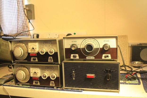
This second AT5 had the PI TANK 80m mod with a slide switch on the back..but oddly it was disconnected. I tried the mod with a short jumper and it allows the TX to gernerate more power on 80m. For my trial on 80m AM I will put the TX into one of my linears to pump the power up to 50 - 60W...that should help a bit. Here is video of the T28 running on 80m AM...not bad. Had a contact on 3.615 using the complete Codar station and no other kit - I was amazed when GW8TBG (Mervyn) came back to my 7W CQ call.
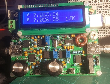
QRP Project Jan 2017 – BITX40
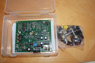
The ready populated BITX40 became available at the end of 2016. Ashhar Farhan's design from 2003 has been copied and adapted many times over the last 13 years - starting out as a simple 20m transceiver to encourage hams around the world to build and experiment – especially those with limited funds.
In 2016 he started another enterprise to get 40m boards assembled by local Indian workers – thereby providing local employment. These complete QRP 5W radio PCBs using surface mount parts come in at a very low price..in the UK it cost me £37.50 delivered to my front door. The first kits came with an onboard varicap VFO that was bit unstable and without a counter hard to tell which frequency you were on. The second batch come with a suitable (if basic) DDS synthesizer on a separate small PCB.
Mine was one of the first batch, so I either used the onboard varicap VFO or my own DDS...which is what I did.
First Test
My first test was just to check if the board was working – all the connectors are provided so only 12v and antenna are needed to check things out. My first impression was that the RX audio had rather too much hiss for my liking..it was not the band noise on 40m, and it was not all coming from the LM386 audio chip..it appeared to be present at the input of the 386. The LM386 was configured with quite a bit of gain so perhaps this was a feature of the simple design (no AGC on the RF / IF stages means you cant have too much gain in this part of the receiver)
The on board VFO was not really good enough for me. Although it stabilised after a while – it was hard to tell what frequency you where listening to – and a multi-turn pot would not allow quick frequency changes - a DDS would be required
DDS
I wanted a DDS that did not require too much programming – this would ensure I could get things working pretty quickly. I chose to go with a DDS control board from the UK Company '6V6'. This board is based around a PIC controller and interfaces directly with one of the popular AD9850 DDS units which are dirt cheap on eBay. The pre-programmed PIC board is easy to assemble with no SMD components and comes with a 16 x 2 LCD display and the rotary encoder.
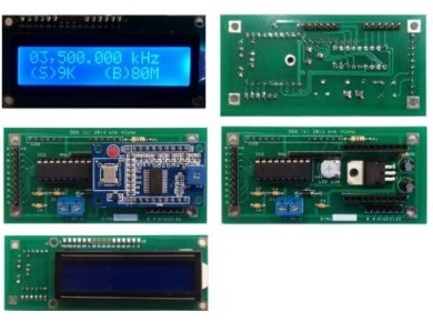
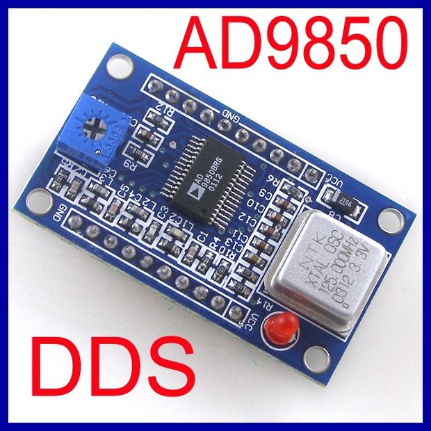
Instructions are fairly minimal but the build is fairly painless. Once assembled the complete DDS and controller make an oscillator that can go from 0 – 40MHz in steps as small as 1Hz, it also allows storage of an IF 'offset' to allow the display to show the actual RX/TX frequency.
I tested the DDS on my scope and it worked a treat with about .5V out. The BITX needs 4.8 – 5.0 MHz to cover the 7.0 – 7.2MHz 40m band.
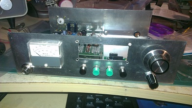
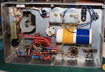
The Box
I had picked up a nice aluminium box with wood wraparound top and sides at a ham radio rally – and it looked just right, with a bit of extra room for either a 25W PA or a PSU. There followed the most time consuming part of the build which was designing the layout and cutting the metal. I had a nice meter from a KW204 transmitter which would look good - and that damn 16 x 2 display needs a perfect oblong cutout with accurate screw holes. I designed the front panel in MS 'Draw' so I could play with the layout and produce a drilling template. I tried to ensure almost every hole and cutout was completed before any other components were added.
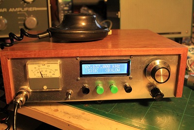
Final build
The final build went fairly quickly, the supplied BITX connectors really speed things up – a bit like an old Heathkit...kit. To use the DDS it is necessary to remove the existing analogue VFO coil. There is a DDS connector on the board and the only extra component required is a DC blocking cap from the AD9850 output. The receiver came up straight away, and after a bit of programming through the 4 push buttons connected to the controller the display showed the correct 40m frequencies. Although the radio has a 12MHz IF, the actual offset must take account of the LSB carrier shift, this works out at around 11.998.5MHz
The damn hiss was still present, and my simple but very effective solution was to roll off the audio response a bit with 100n and 10k preset across the volume control – very mellow sound now.
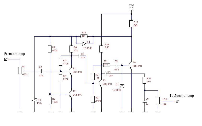
AGC and Mic preamp
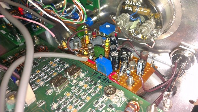
My next test was to try and transmit - I lashed up some wiring to use a condenser mic capsule..the board provides the bias. It sounded awful and with little drive either - even swapping capsules was no help. I put an isolation capacitor in place and plugged in a comms dynamic mic, much much better but still low drive – I had to shout to get peaks anywhere near 5W. My solution was an additional BC108 mic amp which allowed me to add a mic gain control – The pic below is of a generic single transistor pre amp - I used a smaller 10uF emitter bypass cap to keep the gain a bit lower, and added a 10K preset pot at the output. With this set up I was able to have contacts around the UK and EU.
![]()
Whilst listening on another receiver in the workshop I noticed residual carrier on the SSB signal..and try as I might I could not null it out with the preset resistor on the board. I note that there are no small balancing caps as you normally expect to find, so that's a little mod for later.
The lack of any AGC and an S meter was next on the list...searching the net on different QRP rigs indicated that audio derived AGC controlling the audio level to the LM386 was the most simple if not crude option. A simple 4 transistor design which allowed the connection of an S meter was build up on stripboard and to my amazement works a treat, just a little bit of popping on voice peaks, I substituted BC108 transistors in this design The S meter is in PARALLEL with R12, and ideally should be less than 1mA, you must put a 20K trimmer in series with the meter and adjust so that a strong signal is around 75% of full scale- click the picture to go to the webpage or here to see another version of this circuit in English - but note that for the BITX40 you must have the input and output trimmers to set it up properly. I also changed the input preset to 20K to get the levels right - even then you will find the input level can be set quite low.
From the 3 way volume control connector on the board take the red wire to the AGC input trimpot, now take a wire from the AGC output trim pot and wire it to the top connector of the volume control (where the red wire was before the mod). Keep the wires short and use screened cables for the all the connections
The final little addition was relative power indication. A few turns on a small toroid slipped over the antenna connection with a diode and one cap was ample to move the 1mA meter upscale on voice peaks. Now it looks and works like a nice little radio
AGC and Mic Preamp
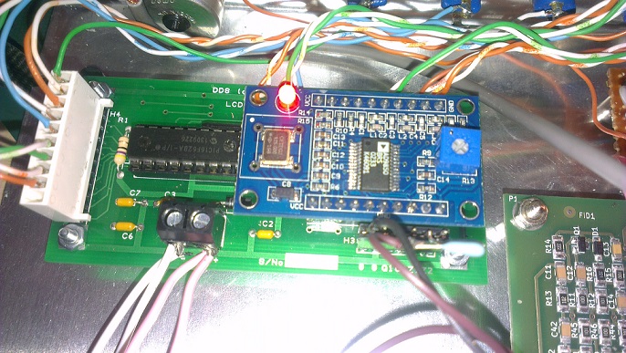
DDS and Controller
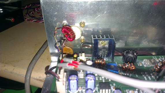
Relative power toroid and diode
October 2016 - A real oddity - The British 'Sphinx' HF Transmitter
Went back to one of its earlier owners in Feb 2019
This was a real odd one - the 'Sphinx' HF Transmitter made for a brief period in the 1960s by SSB Products of Derby England. This is another bit of kit that came to me through a friend and it sure is a strange piece of ham radio gear. SSB Products seemed to have an obsession with naming things after ancient Egyptian culture, they sold a 'Pyramid' HF linear as well
The Sphinx must have been an attempt to cash in on the UK market for ham radio kit in the mid 60's. KW were going strong and maybe the founder (G3EKX) thought there was room for a competitor...but this was made down to a price (but sold at a high price!) and even at the time it looked decidedly basic - in fact its almost homemade, I think it was available as either a kit or ready built. Corners were cut in both the design and construction of this transmitter.
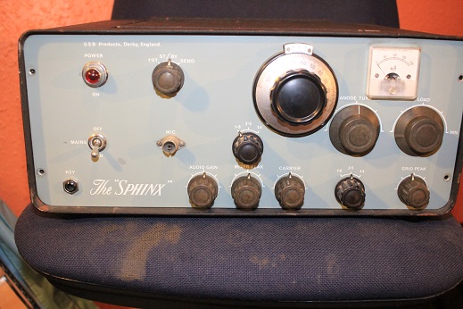
It uses a very basic mixing technique with the SSB filter at 435kHz and only one carrier crystal (436.000 on mine) on 3 bands. 160 and 80 come out as LSB and 20m as USB..there is no 40m band as that would have come out as USB without either adding another SSB filter or a 2nd carrier oscillator...too complex so leave it out!. 15m and 10m would have needed more crystals and switching - so leave that out as well (or buy an extra HF adaptor!).
The SSB filter uses only 2 crystals - so not the best suppression
Contacts to either mute a receiver, switch the antenna or have PTT are all missing...that needed another box called the 'Delta control unit'
It has 2 separate band switches
Only one HV winding on the transformer, - so how to get from 500V for the PA to 230V DC for the rest of the TX.. Answer : use a very big dropper resistor.
No winding for a -100 V bias supply either so how to do that??..Answer : use another little transformer to step UP from 6.3V to 100V
How to bring all the PSU and control sections out to the back???..Answer : put highly dangerous voltages on ' chocolate block' connectors that you can easily put your finger on..and maybe die!
VFO calibration ??? forget it. Make your own chart (or use the one supplied) to match frequencies to the vernier drive
Having said all that - I ran it up from a bench PSU with low volts on the PA and got about 15W out on 80m...by manually switching the antenna I was able to have a few contacts -and no one complained about poor audio, a bit of carrier, or drift...I should have told them it was a IC7300 !...nice
The Sphinx must have been an attempt to cash in on the UK market for ham radio kit in the mid 60's. KW were going strong and maybe the founder (G3EKX) thought there was room for a competitor...but this was made down to a price (but sold at a high price!) and even at the time it looked decidedly basic - in fact its almost homemade, I think it was available as either a kit or ready built. Corners were cut in both the design and construction of this transmitter.
October 2016 Paraset WWII Spy Radio Replica
This next project is all thanks to Colin G3VTT - on a visit to his home I was impressed by the lovely little QRP valve rigs he handbuilt - each one was a work of art. He persuaded me that I should build one and even gifted me the octal valves to get started. He reccommended I look at the 3 Tube 'Paraset' design which uses a 1 valve CW transmiiter and a 2 valve 'Regen' receiver...this design has copied by hams across the world - some have built amazing replicas and others have used some modern twists in the design - after all the world of electronics has moved on a bit since 1942..wow...thats 75 years ago !.
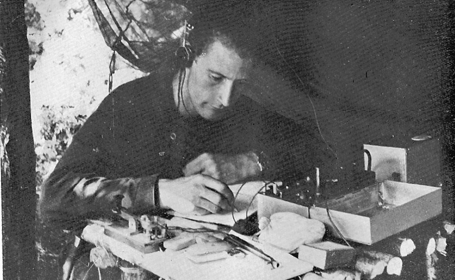
The original MI6 (Secret Intelligence Service) wartime name for these units was the MK VII - designed in 1942 and initially made at Whaddon Hall. After the formation of the wartime SOE (Special Operations Executive), it was discovered that this simple little radio was ideal for parachuting into occupied countries for use by local resitance groups and spies - it operated between about 3 and 8MHz. The simple design was not without its drawbacks though - one of the worst was that the simple regen receiver radiated a little tiny bit of RF - this meant that if a DF unit got close to the location, the receiver alone could give its position away. More info here http://www.sm7ucz.se/Paraset/Paraset_e.htm.
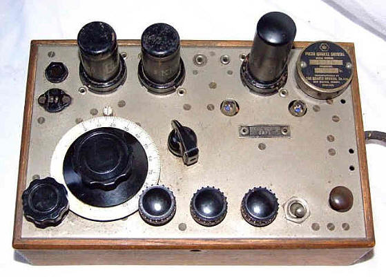
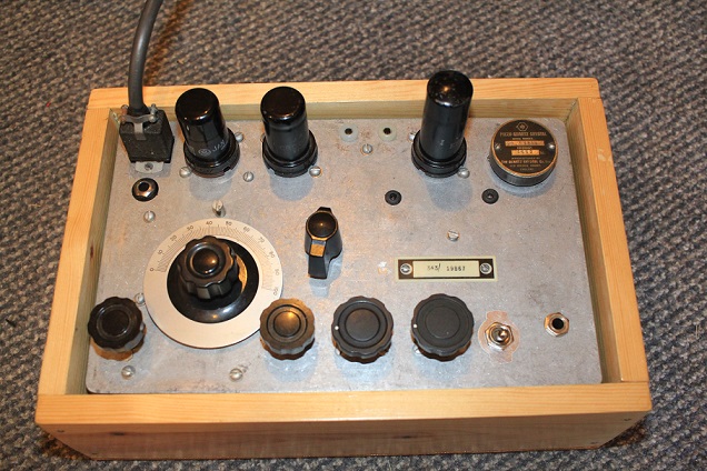
PICTURE OF AN EARLY WOODEN BOX VERSION
I looked at the designs across the web and starting raiding my parts store for the bits...to my surprise I had most of the parts to get started...but first the metalwork!!. In most ham radio projects (especially tube ones) the metal work is the longest and hardest part of the build - it sets the course of the whole job. I wanted a reasonably professional job..and found a large die cast box that was little bigger than most of the paraset replica's..this was a good thing because it gave me some extra room to play with, especially options for PA antenna matching
I spent quite a bit of time researching the schematic, layout, parts and typical builds by other hams....research always pays off. I was not prepared to pay a fortune on ebay for rare parts - that would defeat the whole object. My biggest substitutions were on the PA Tank capacitors - the Jackson 100pf ones are not readily available or demand a very high price. I had 2 broadcast twin gang capacitors which fiited nicely - although as they are nearer 250pf, tuning will be more critical. The authentic copies use a slow motion 'friction' drive to turn the main RX tuning dial..I didnt have the parts for this so opted to use a very low value variable cap as a bandspread arrangement (control at bottom keft on front)..even then I found it hard to use both 40m and 80m on the one receive coil...so I may have to revert to a bandswitch for the receiver.
I also had to scour the internet to buy some older style TX crystals for 40 and 80m...and ended up with 3.530 MHz, 3.562 MHz, 7.010MHz
The original unit was built to load into a random wire so uses a link coupling on the simple PA - I decided to include an option to use a more standard 'Pi Tank' arrangement that would allow the radio to be connected to a matched 50 ohm antenna - pics below shows my completed unit.
Geoff G3YVF suggested some mods to get proper bandspread..I chose 80m and made up a calibration chart. The sensitivity of the receiver is just staggering, its just the skirt selectivity that means its hard to use on a crowded band...but hey there is just one tuned circuit !
PICS OF THE G3ZPS PARASET REPLICA
Connect with me today
Call me on 44 (0)7970 190437