 Yaesu Musen
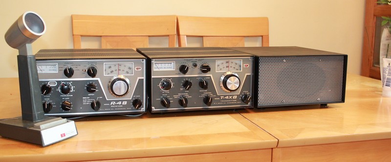
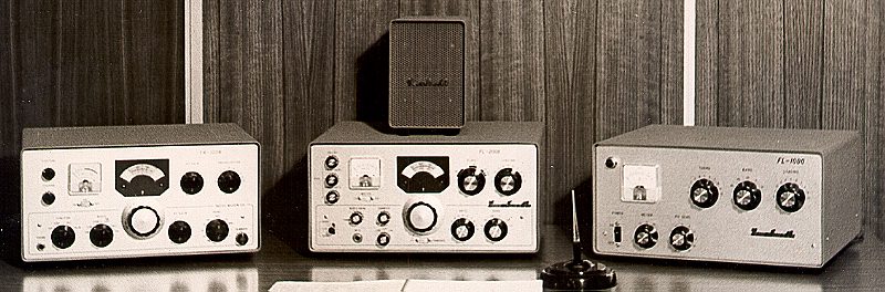
Yaesu started as a communications equipment company in 1959 under the stewardship of Sako Hasegawa JA1MP. His initial plan appears to have been to produce domestic ham and commercial radio equipment. In this regard Sako had remarkably similar ambitions to Robert Drake in the USA and Rowley Shears (KW Electronics) in the UK. Yaesu quickly started producing valve transmitters and receivers in the early 60's and established the 'F line' as a brand that would soon become familiar to just about every radio ham on the planet. The early HF SSB equipment used the same mechanical filters as Collins and KW, but Yaesu quickly switched to crystal filters. Their 1960's FL100, FR50, FR100 and FL1000 were not remarkable in themselves and other manufactures did not pay any great attention - even as the units started to appear in USA, EU and Australia...but Yeasu had hardly got started !!!
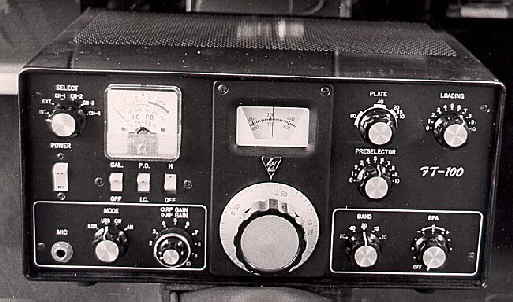
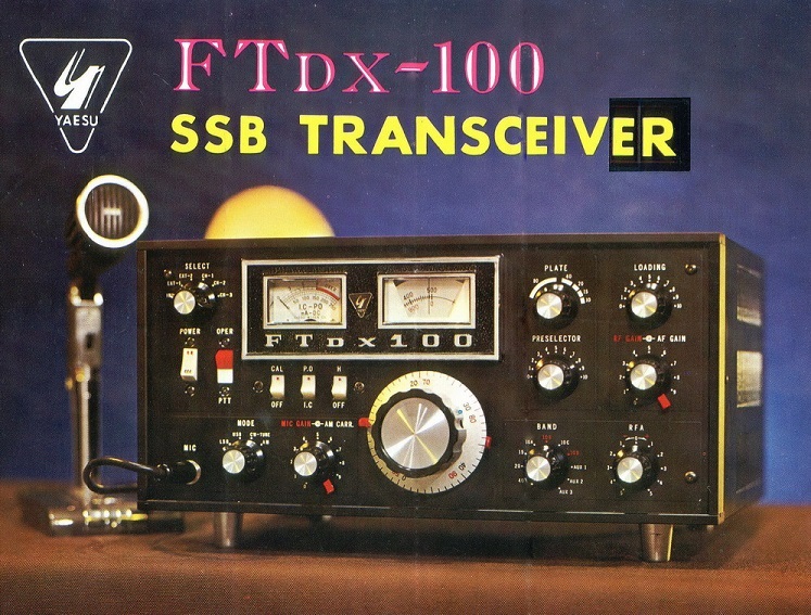
One thing set the Japanese manufacturers apart from KW and Drake in this period..the speed of development of new products...the shear pace of Yaesu R&D coupled with either the introduction of new models or revisions to existing models was dizzying. Yaesu quickly started targeting different aspects of the ham radio market - with innovative part transistor designs (valve / solid state 'hybrid'), heavyweight ' boat anchor' stations for use as fixed stations (like the FTdx400/500 series with their claimed 560W PEP input) and low power 'novice' equipment for the home market. The first hybrid transceiver design was the FT100 and appeared in 1966...it was a quantum leap ; AC and DC supplies built in, 50 - 80W output, just plug in a Mic and go!!. The FT100 was a great little transceiver for base or mobile use and went through 3 updates over a 4 year period ending with the FTdx100. The next model let loose on the ham world in 1970 would become a legend.
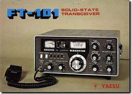
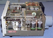
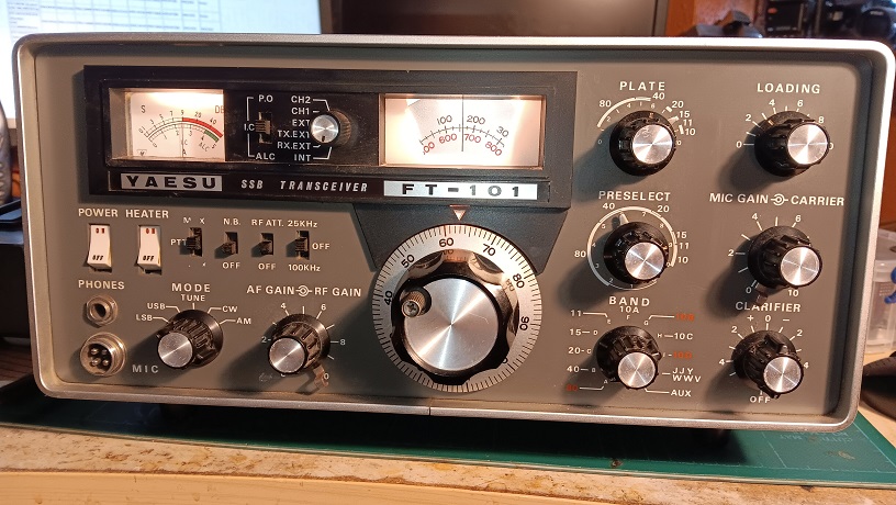
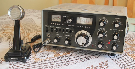
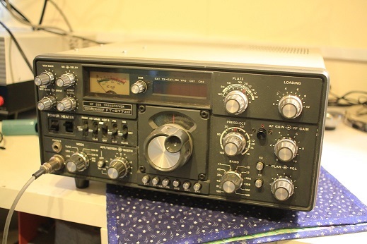
The next HF transceiver - THE FT101 - is arguably the single product that started the slow death of KW, Drake, Collins and other manufacturers of Ham radio equipment. Yaesu built on their experience with the FTdx100 and came up with a global winner. The FT-101 series of transceivers first appeared internationally in 1970 (in the US in January 1971). It gained overnight approval of amateur radio operators for its flexibility, workmanship and design. The modular design of solid state circuit boards on a common chassis with a rugged tube output stage was a revelation for the price. Everything was in one box, there were no extras to buy. It was stable at switch on, did not run hot (if you had the fan option) and was built to a very high standard on a large production line..other manufacturers were left in the dust !. Of course markets like the USA continued to buy homegrown products, but it was too late - the tide would become unstoppable. Production of the FT101 and its B and E versions ran to well over 200,000.
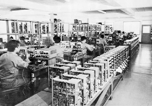
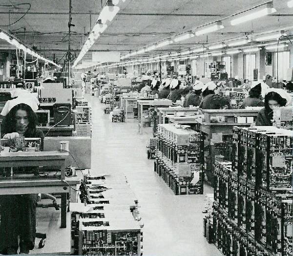
Yaesu clearly meant business in the global ham radio market as these two early pictures of the large production line show
The FT101, was the start of a revolution in Ham Radio equipment - the other major Japanese manufacturers (Inoue/Icom and Trio/Kenwood) were just behind and along with Yaesu were destined to become the major global players in the market. Yaesu kept up the fast pace of development, revising designs and bringing out new models. Yaesu really listenend to their customers in this period and the 'Fox Tango' club became critical to the development of the 101 with a host of mods and changes suggested by members through to the B and E/EE variants. The very first FT101s had a number of TX spurs identified by users which means later B and E model have 'traps' to minimise them. I am surprised these weren't spotted before the initial production. The RX also suffered IM problems and this was not fully resolved until the later variants came out. These early hybrid radios were effectively a complete 'Shack in a Box' and oddly there are now very few HF transceivers with a built in power supply. Despite the plug in PCB construction the radio has extensive (and costly) hand soldered wiring..inflation adjusting the price from the early 70s to 2018 shows that an FT101/B/E would have been in the region of an equivalent £3000 for UK hams..so some of todays radios look very good value indeed.
As of mid 2018 I have restored 3 early FT101 models (2 Es and 1 B) and can attest to their super build quality and reliability. Ironically the 2 that looked the dirtiest have came up to perform the best. After taking the front panel off and all the boards out I go through extensive cleaning and checking of all the mechanical parts, switches, pots, relays etc. I also change the PA grid capacitors and re align to the manual. Knobs are scrubbed with washing up liquid and the case and bezel are also repainted.
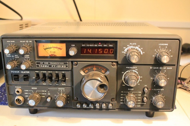
The first FT101 I owned in 1979 was from the 'Z/ZD' line - this major revision saw Yaesu re-design to keep costs down by doing away with plug in boards and moving to 6146 output valves - not really the same radio but the name had become iconic. The 101Z series all had excellent receivers (although not the widest dynamic range), and I really couldn't find any weaknesses, for non contest use it was perfect...in 1982 I got married changed jobs and packed away the 101 in its box...for 20 years
G3ZPS Yaesu Collection
Another FT101 Jan 2024 - Jan 026 Update
This early FT101 was given to me at recent vintage radio event as ‘ probably not working’. If it couldn’t be saved it would a least be useful to keep my other 3 going.
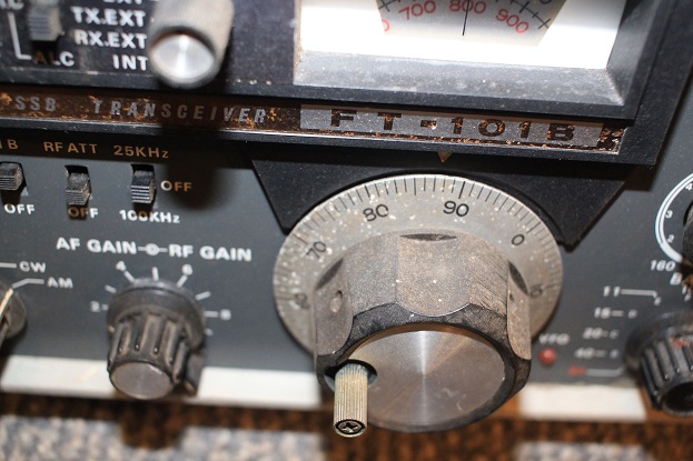
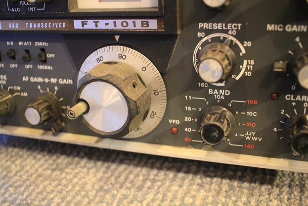
As is usual with every vintage radio in my collection, the initial work is a voyage of discovery to assess condition, age, mods and any parts missing. This FT101 turns out to be part of the very first production runs to appear in the UK and will date to around 1971, Serial No 6252. The plug in boards are pretty well documented and this has one or two only present in the very earliest radios.
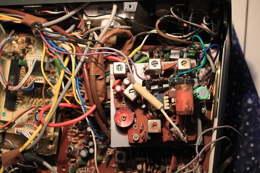
The internals were dusty but with nothing missing, the PA area was clean and both OP valves were present and correct with no signs of stress. It had clearly been modded to cover 10MHz and 1.8MHz with some extra RF components. The early RF front end board had been modded to use an MC1496 DBM chip, although whether this actually improved receive performance was never clear. Early FT101 models suffered receive IM problems, especially on 40m at night. Things didn’t really improve much until the E model came out.
All of the trimmer boards had been remade so that extra ones for 30m and 160m could be added, some sort of home-made bandpass filter had been and left hanging near the VFO, and proved to be intermittent. Without any clear idea of what is was for I removed it.
The early IF board (PB1080A) had seen a lot of work with all the noise blanker parts missing. Soldering of the mods on this board was poor and there was a intermittent on receive when it was tapped. I re-soldered all the suspect joints and the problem was solved. The removed parts were related to the noise blanker which was on this board before it moved to a separate module in later models. Early FT101 noise blankers were never that good anyway. This radio has the PB1182 NB board - the NB board was changed again and relocated for later models
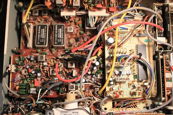
I assessed the quality of each board and cleaned the edge connectors, a bonus was the CW filter and no components appeared to be badly damaged. I cleaned all the switches and relays and then brought the rig up to full mains voltage. Switches were still problematic but it came up straight away. After a day or so of soak testing I tested the TX - the performance on 15m is amazing with well over 100W PEP out and I worked into the USA easily. The RX quality is great and the VFO stability is just superb. The RF attenuator switch would not respond to cleaning so I had to bypass it completely. New dial and meter bulbs along with a general clean up and it looks great !
Alignment on 40m transmit is a conundrum – its the only band and with very low TX drive – further investigation required. The trouble with a modded radio is you never know what a past owner added or removed !
Never the less it appears the these very early radios were built with a lot of care – 53 years old and few components changed (not sure if the OP valves are original !). You can see why Drake and KW were killed off – they never caught up.
Jan 2026 update
The audio ouput on this FT101 started to suffer from severe distortion and suspicions soon indicated the AF board ws the problem. Yaesu quickly abandoned this early design with its 2 PNP germanium OP transistors. The FT101 group on Facebook helped me locate the schematic of this board and although it can be substituted with the later model AF boards (which I have), a mod to the wiring is required as an external VOX anti-trip connection was added on later models. An oscillioscope check quickly identified that the transformer (yes really !) drive to the OP transistors was OK. The only solution was to replace them both - although the 2SB deveices were available in the UK a cheaper alternative was to use similar spec Mullard AD162 transistors. This has cured the problem.
July 2020 FT101ZD/902DM Line
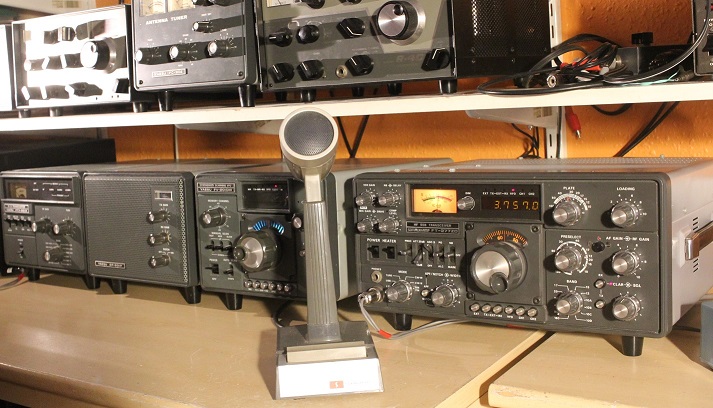
After using over 17 vintage HF stations during the COVID lockdown, I have raided the workshop to get all my FT101ZD/902DM line accessories running together. The 902DM has stayed in the workshop cos its sooo heavy. Here we have the now fully restored FT101ZD MKIII (see more about it further down this page), the FV-901DM Synthesized VFO (100Hz steps !), the SO-901P speaker, the FTV 901R transverter and above it the FC-902 antenna tuner. Of course all of this would fit into a tiny box in 2020, but hey - it looks and works great.
May 2020 - Yaesu FT-70G
 This is an odd one.
I spotted it in the shack photo of a local ham and casually mentioned
that I would like one, to my surprise he offered to part with it and
after we had done a deal he dropped it off during my COVOD 19 quarantine
period. There is not a huge amount of information on the web, but I have
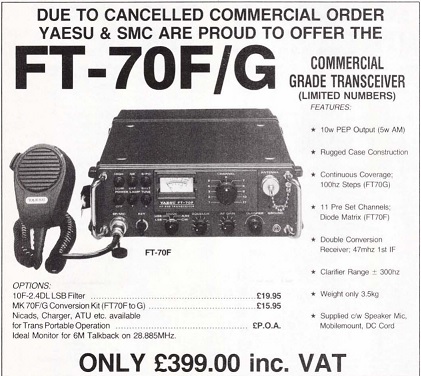
been able to locate a service manual. The FT70G is a ruggedised 'near' military spec HF radio with
up/down switchs for 2 -30MHz in 100Hz steps. With its 'man pack'
accessories it was apparantly used by the armies
of Japan, India and most notably, the Contras. It would have
been a lot lot cheaper than the true military radios of the period, but
good enough in the field. Yaesu knew the market they were aiming at. This
ad was in the UK Mag Practical Wireless in 1989 - 'Cancelled Order' - limited
numbers available ! although my mate James M0STP has 2 of them.
I was staggered to see that one sold on eBay with the matching ATU (but
without the main PSU, or matching speaker/mic) for over $1000 !. I was
also amused to find that The Royal Geographical Society (London)
specifically referenced this radio in its 2003
guidance document for polar explorers ! They said - '..We
have used
Racal PRM 40XX series radios and Yeasu FT70G
portable commercial HF radios. These
work very well and have specifications
suitable for polar use..'
This is an odd one.
I spotted it in the shack photo of a local ham and casually mentioned
that I would like one, to my surprise he offered to part with it and
after we had done a deal he dropped it off during my COVOD 19 quarantine
period. There is not a huge amount of information on the web, but I have
been able to locate a service manual. The FT70G is a ruggedised 'near' military spec HF radio with
up/down switchs for 2 -30MHz in 100Hz steps. With its 'man pack'
accessories it was apparantly used by the armies
of Japan, India and most notably, the Contras. It would have
been a lot lot cheaper than the true military radios of the period, but
good enough in the field. Yaesu knew the market they were aiming at. This
ad was in the UK Mag Practical Wireless in 1989 - 'Cancelled Order' - limited
numbers available ! although my mate James M0STP has 2 of them.
I was staggered to see that one sold on eBay with the matching ATU (but
without the main PSU, or matching speaker/mic) for over $1000 !. I was
also amused to find that The Royal Geographical Society (London)
specifically referenced this radio in its 2003
guidance document for polar explorers ! They said - '..We
have used
Racal PRM 40XX series radios and Yeasu FT70G
portable commercial HF radios. These
work very well and have specifications
suitable for polar use..'
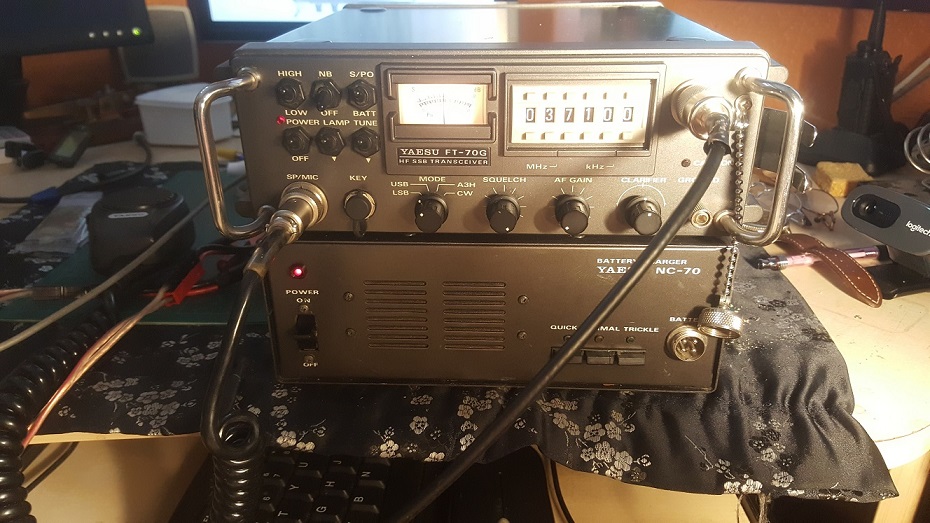
Mine has the optional LSB filter installed, speaker mic and the correct mains PSU / battery charger. The battery pack and other ancilleries are very hard to find in Europe as not that many were sold here, so a rare radio. 10W out on SSB so needs a linear for rag chewing but great for portable QRP. Its way heavier than an FT817, although in its favour there are no menues, double functions buttons and a tiny screen, this radio is dead simple to use. Its a bit like my IC7200 but in 80s format. I love it. More info here
February 2020 - FRG 7700
Came to me fairly cheaply and I soon discovered it had one fault. On any 1MHz band the radio would not function above about 840kHz. The give away was that this problem was present on every single setting of the MHz dial.
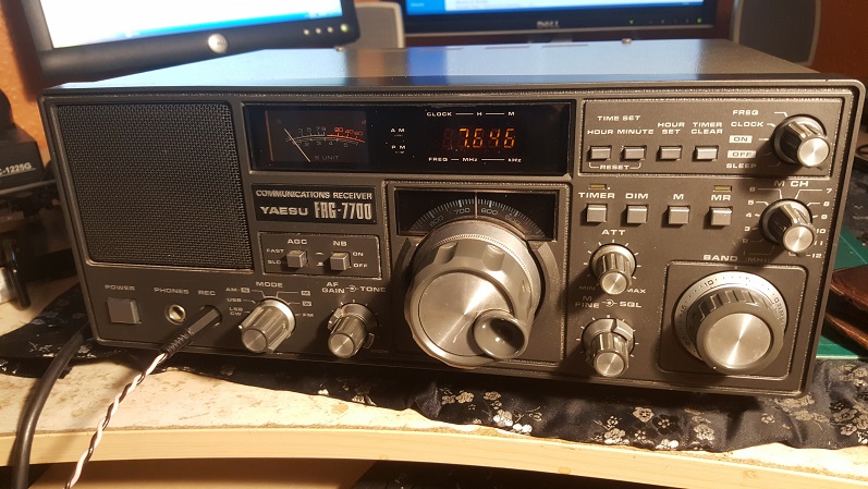
The excellent FOX TANGO survival guides came to the rescue - this was a very common problem on the near 40 year old 7700 and one of the PLL loops probably needed alignment. Sure enough the PLL that scans each 1 MHz segment was the culprit - a few minutes with a scope and a trim tool and it was fixed and the radio is now working A1. OK, its not a top flight ham receiver and has no CW filter, but its very quick and easy to use, stable and sounds great on all modes with 2 extra AM filters and FM - the biggest gripe is the very fast tuning.
There is a documented mod to use the memory fine tune control in normal operation (it does not have the memory option fitted), but that means getting inside the VFO. This 7700 appealed to me as the cosmetic condition is 9/10 with hardly a mark and it looks great. The impulse noise blanker is superb and completely removes the PLT noise I have in some of the SW broadcast bands
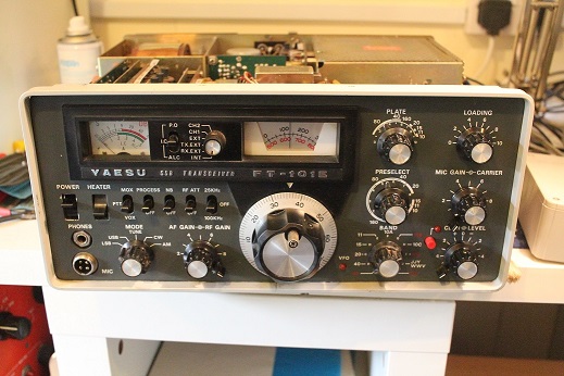
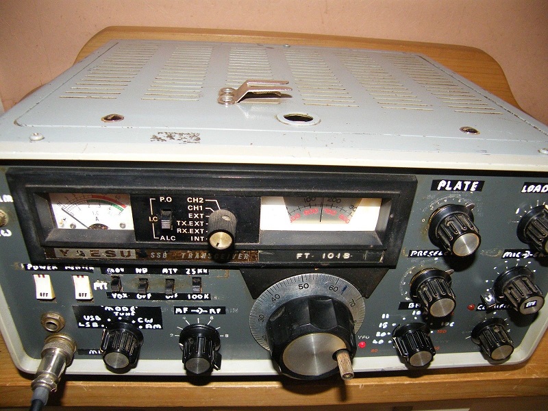
December 2019 FT-401B
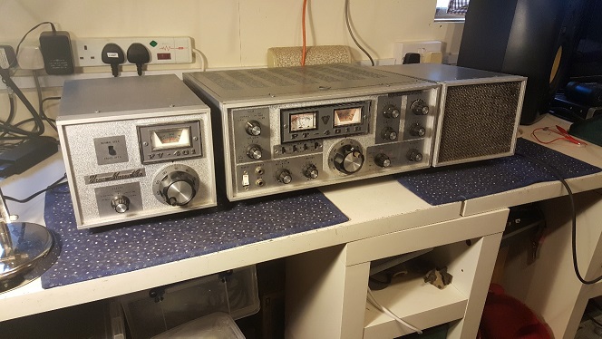
This mid 70s monster 20 valve FT-401B along with its VFO and Speaker was gifted to me by a good friend. It came from his local friend who was disposing of an SK estate. As it wasn't working it wasn't really considered worth anything. The report to me was that on variac start up it blew the mains fuse before it was up to full mains voltage. On inital inspection its cosmetic condition impressed me although my main worry was the state of the mains transformer and the 6KD6 Sweep tubes. This radio is the last in a line of big 'Silver Faced' Yaesu transceivers that first appeared in 1968 as the FT400 in the USA and the FT500 in Europe. Also later badged as Sommerkamp (the FT505 /747) in Europe and available as the Yaesu FTdx560 and FTdx570, ending with the FT401B in around 1973/4. There are only minor differences between any of these radios and mainly relate to options like the Noise Blanker, AM operation, PA fan or CW filter. The OP 6KD6 'Sweep Tubes' can handle a lot of current but their dissipation is limited and the claimed input of power of 500W must be treated with caution. The construction quality is not brilliant and there are a lot of components tacked on underneath the main PC. However unlike Heathkit and KW most of the resistors were still within tolerance. Here is good reference page on the various models and some of the early adverts of the FTdx400
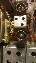
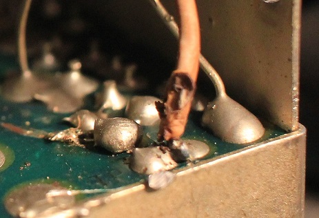
Before the initial test I removed the Toshiba 'green stripe' OP tubes (the most sought after) and had a look under the PSU PCB, it was easy to see one of the problems. The 800V EHT had been arcing to a screw in the chassis and carbonised the cheap paxolin board..it even burnt through an unrelated track that just connected to the accessory socket. The rest of the PCB looked OK and all the diodes tested as good, so I unsoldered the EHT connections from the transformer and brought the radio up...after forgetting that without the remote VFO plugged in the 7 pin socket needs a jumper - the RX came up and sounded pretty good. The remote VFO is quite rare in the UK and it also works well
The clean up of the PSU board took a while as the carbon, had
burnt deep into the paxolin - for good measure I also changed the HV
capacitors, ballast resistors, the PA grid coupling cap and checked the neg bias with the tubes
removed. The radio then came up with no issues
and I was able to refit the 6KD6 OP tubes and cross my fingers again !. I reset the bias and fired up the radio up on 80m..loads of
 power and
great audio reports with a Shure 444. Difficult to know why the PCB
arced across quite a long distance (0.75 inch), but once it had carbonised the material it was a permanent conductive path to ground.
The most likely culprit is moisture, but in reality I will never know.
power and
great audio reports with a Shure 444. Difficult to know why the PCB
arced across quite a long distance (0.75 inch), but once it had carbonised the material it was a permanent conductive path to ground.
The most likely culprit is moisture, but in reality I will never know.
This left one issue that always annoys me - on 40m and above the radio is a bit deaf. A few valve swaps and voltage checks reveal nothing obvious and the AE relay is in perfect condition. The loss of 10, 15, or even 20dB doesn't really affect 80m, but by 20m it has very big effect. Watch for the next update!
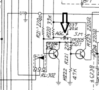
Spring 2020 update A few faults corrected during the lockdown period. The setting of the AGC proved to be critical and improved the receiver, but I clearly needed a 401B schematic. Thanks to Donald MM0ALX (who knows these radios well) I changed ceramic trimmer TC205 and traced the VFO jitter to the 9v regulator. I replaced this circuit with a modern LM317 set to exactly 9V (see pic). The PCB is crowded around the old regulator circuit - not helped by components under the board. I checked the schematics and the PC board layout dates from the 1967 1st generation FTDX400. Yaesu added an extra reisistor and zener diode around the 9v regulator in the slightly later FTDX560 and just tacked them on under the board. It appears the large PCB was never changed for any of the 400/560/570/401 radios, updates were made with either add on boards or components under the PCB. This Japanese site goes into great detail on the 400 series of radios, every minor production and model change is documented (and there were a lot). It looks the earlier radios are less cluttered with mods and I would quite like one !
Summer 2020 update I was still unhappy with the AGC performance of this radio. The cluttered under chassis wiring is a pain and its a real shame Yaesu didn't re-design the main PCB. The 401B AGC is amplified by a FET on a little tag strip (not even a small PCB). I changed the FET for no improvement but in the process worked out that the capacitor from the RX IF strip was not on the gate of the FET. I moved it and the effect was immediate. This was the fault I had been chasing for weeks - there are so many bodges its hard to tell why or when this was mis-wired. I can't imagine Yaesu did it.
Autumn 2021 update Out of the blue the 401 blew its mains fuse and clearly had another problem. I quickly traced the fault to the PSU board (again)..a few mins testing the HV diode chain revealed one or two had failed short circuit. I changed all 8 for 1N4007s and normal service was restored. The original 10D10s are rated at 1.5A and the 1N4007 only 1A, but with a high surge rating. I figured that 1A at 800V equated to 800W input to the 6KD6s and the rated ICAS 500W input was unlikely to stress the newer diodes. I also traced an intermittent fault that affected both TX and RX to the 'BPF5' Bandpass filter unit...looks like the fault is inside the can..another annoying job to fix
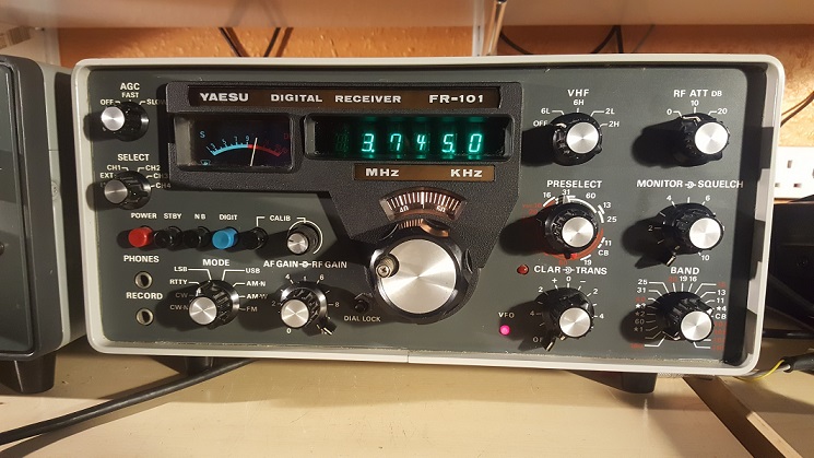
October 2019 FR101D
A Ham friend spotted this for sale on a site selling unwanted items - it was just a few miles away and offered at a good price. The seller indicated it was in near pristine condition and I drove over within 2 hours and bought the receiver before someone else spotted it. I believe this is the 'SD' model as it has all the filter options in place, FM/AM/CW and the 2m converter (although the 6m/4m converter is missing). The only work I needed to do was use de-oxit on all the switches and controls..and what a delight to see that not a single bodge or mod was evident.
This is a mid 70s design very closely related to the RX in the FT101. Yaesu went to a lot of trouble to ensure that the FR101 can fully integrate with the FT101/B/E as well as its companion TX the FL101. Although not true general coverage it has crystals for most of the old broadcast bands as well as all the pre-warc ham bands (160 as well). There are no QRM fighting facilities at all and the NB doesn't really do much for modern noise types.
The FR is extremely sensitive and quiet - you have to use the attenuator on the low bands. This probably limits its strong signal handling properties compared to modern gear. The other surprise was the stability, for a free running VFO its rock solid after a short warm-up - one of the best in my collection. The only thing I dont like is the dark red lettering on the band switch and preselctor..I can't read it. Oh yes..and it tunes in reverse, clockwise tuning goes down in frequency...odd
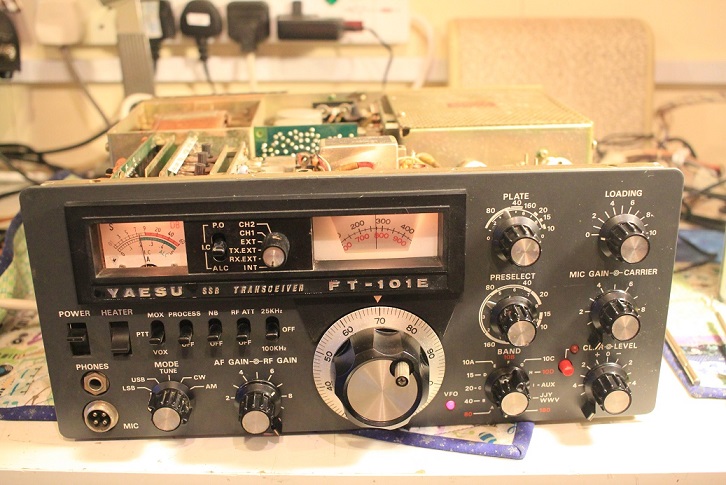
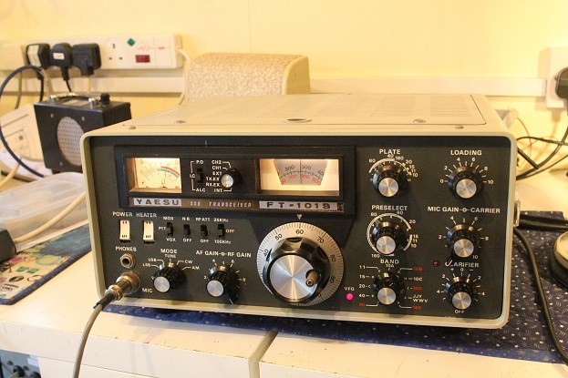
June 2018 - Junk Sale FT101E and FT101B
These 2 radios turned up at at a local clubs table sale, both were quite dirty, had rusty cases and clearly had not been used in many years. Despite a very low price for both, no one in the club was interested. When I enquired about the history the seller told me they had been donated to the club ..he then offered them to me at an even lower price!...but I still resisted. The following day I gave in and emailed the seller to find out if anyone had bought them...that was it...I drove over and picked them up.
Both radios were complete, had clean front panels and looked as if they could be brought back to life. I was probabaly expecting too much to see Toshiba 'Green Stripe' PA valves in both, but was delighted to see them in the B. The E had no valves at all, there were no mains leads and only one accessory plug. All plug in boards were in place
I started with the E..and the first job was clean up. I removed all the plug in boards, the knobs and front panel and did an assessment of the overall condition. Nothing was missing or fried and the underside was untouched and very clean. There then followed quite a few hours of scrubbing and washing along with liberal use of contact cleaner in all the switches and controls. Both relays checked out fine.
At the end of a long first day I was ready to test the receiver..and with no valves present the TX would be left alone
The receiver came up straight away - a bit more contact cleaner was needed but it was working at a reasonable sensitivity and sounded absolutely fine..I was amazed. I was able to trace a previous owner of this radio through a sticker on the back..it was owned by the late Brigadier Johnny Clinch OBE G3MJK..John had a very distinguished Army career including D Day and operation Market Garden. He also became the Chairman of the Charity for Radio Amateurs with Disbailities - the RAIBC. Its likely that this radio was one of a number that could be loaned out to RAIBC members or maybe Johnny used it himself, either way its a great story. Johnny died in 2007 but you can read an obituary here
I turned my attention to the B and followed the same process..again the radio was in good order throughout. I had to raid my Yaesu parts bin for knobs as some were damaged or missing the silver insert. I never go for the daft 'complete recap' that some appear to be obsessed with. HV and PSU caps perhaps - but in my experience the ELNA caps in Yaesu gear give very little trouble. The B front panel in particular is in superb condition for a 45 year old radio..normally there is paint loss or the lettering is faded by the power and slide switches..not so here. Its entirely possible that the Toshiba OP valves are original if its had only light use over the years
The B receiver also came up straight away, but again required more use of contact cleaner (especially the Mode switch)...this time the receiver was really good and the performance on 20m was superb
Having determined that both were capable of being restored to
operation I spent the 10 days gradually bringing them back to full
working order, completing alignment and restoring the cosmetic condition..mainly case and
bezel repainting. I zeroed the TX and RX frequencies by listening to the
VFO on a general coverage receiver and have had 80m contacts on both
radios (over 100W PEP out). Both fans were faulty (one noisy and
one failed), and will be modded with 12V computer fans running from the
12V heaters on the accessory socket. Without a fan the PA
compartment gets really hot.
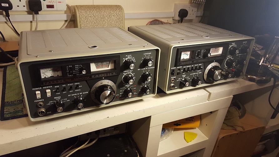
FT200 June 2018
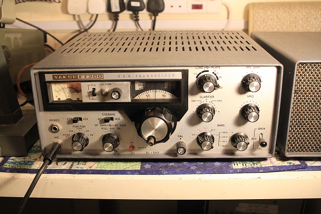
This radio came to me through the Friedrichshafen Ham Show in Germany. A DL friend of one of my travelling companions wanted a good home for this radio as he couldn't even give it away in Germany. I initially refused as I was not keen on hold luggage on the 2 airline flights..I relented when he offerd to send it by courier for a very reasonable price. The radio was actually delivered whilst I was in Germany. On first inspection, I was somewhat dismayed to see the number of undocumented mods done to the rig - it had clearly been got at. An active CW filter was in series with the audio, an added PA heater on/off switch also operated a fan..another mod related to the 9V regulated supply for the small numbers of transistors. The sidetone oscillator had been modified to act as the CW carrier and the USB /LSB switching had also been reversed (?). This was not how the radio was supposed to work on CW !.
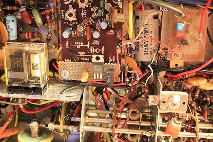

After switch on the radio worked after a fashion but with the RF gain working backwards...and even then not correctly. I almost gave up at this point as the wiring is not easy to identify and trace. After a strong coffee I started to trace the RF gain wiring which had been changed in a way that did not match the schematic. To try and see what was going on I downloaded a picture of the underside of a smilar radio and could clearly see the wiring on the RF gain pot. I took a chance and rewired the radio back to stock..voila!!! the RF gain now worked properly.
Over the next 2 days I slowed the AGC release time, moved the carrier crystals to get the SSB audio recovery to my liking and carried out the product detector mod in the Henry Tempo 1 (FT200) service manual. The radio now began to work really well with over 100w PEP on 80, 40 and 20..in fact it garnered amazing audio reports!. As with bodges and mods on my other radios its difficult to understand why they were carried out. I suspect the owner wanted to run low power on CW - which is not possible on the unmodified FT200. Wiring the sidetone osc into the mic circuit on CW allows the power to be turned down to a few watts. The killer for me was that in the end te radio was rendered useless until I got hold of it. I have left the active CW filter, which I have since seen on other FT200 radios.
The the radio is back and working great on SSB. Yes, AM and CW are poor (but useable after some mods), only one filter, no fan and pretty cheaply made - BUT, I have a changed fewer out of spec components than Heathkit and KW. Adding a fan and changing the PA coupling caps has resulted in a delightful simple little SSB radio for the low bands...you may see them as horrid ex CB junk...no problem ..send them all to me !. I eventually undid all the strange mods to get the radio back to stock - look at the pics to see what bodges had been grafted in.
FT200 Differences
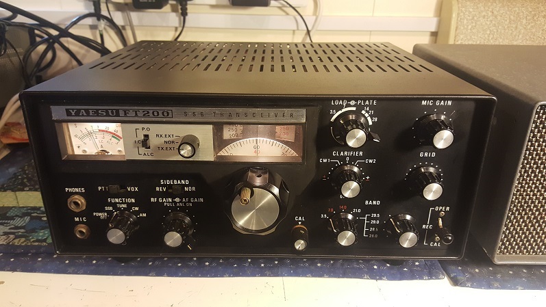
During Febuary 2019, I restored a second FT200 (late black model - rusty and cheap £35 / $40) and uncovered some of the circuit changes that Yaesu carried out over the life of this radio - there are at least 3 schematics and other circuit differences
1. My black one has the 'ext VFO' 7 pin socket (not present on my grey model), this must be jumpered for the internal VFO to work. I have since found that many of the grey fronted ones have the VFO socket - so perhaps my grey model is very early indeed
2. Pin 7 of the power connector is wired as the loudspeaker connection on later models..so mixing the PSU from an earlier radio may result in no audio..but the ext speaker phono connector is still wired on the later radio, so use that.
3. Very late models used a solid state replacement of the rare balanced modulator 7360 valve..the new little board actually plugs into the 7360 valve socket. There is a subtle change around the 12AX7 microphone amplifer in this model - the second cathode 2k2 resistor is not wired to ground..clearly shown on the late model schematic - its bodged on the PCB. I assume its to cut the audio drive to the new solid state BM
4. I have not uncovered what the significance of the black and silver models where, or whether they went through the same changes. Its odd the Yaesu went to the trouble of producing 2 completely different colour schemes..some of this info is lost in the mists of time !
The FT200 came to market in around 1969 as part of Yaesu's ever expanding ham radio product range, and quite a lot ended up with CB operators. In the USA it sold as the 'Henry Tempo 1', and in Europe Sommerkamp rebadged it as the FT250. The radio is a basic 9MHz single conversion design with no provision for extra CW or AM IF filtering. The 'sweep tube' PA must have run very hot without a fan and the performance on 10m is not brilliant. I am amazed that these rigs survive - my good friend Dave G3ZPA is still using his one - which he bought new in Australia in 1969. Another article on the web mentioned that one ham used his for EME contacts using a 70cm transverter driven by an FT200. I even found some adds for this radio in Ham magazines as late as 1978.
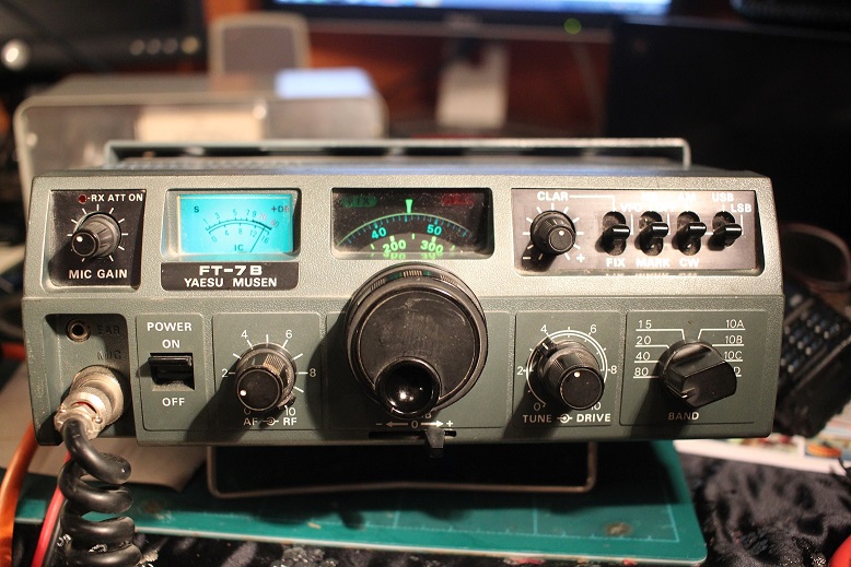
FT7B January 2018
Took delivery of this very clean little radio from a ham buddy who was never going to use it. He was convinced it had a receive audio fault but on switch on it worked fine. As there was nothing obvious wrong I keyed up the TX and was staggered with 50W and super audio reports. Made around 1980 its all analogue with discrete components on plug in boards and built like a small tank - its a very well engineered radio and the quiet receiver is a joy to listen to. The only real drawbacks are the drift in the first 30 mins of use (although it appear rock stable after that) and limited coverage of 10m (unless you buy more crystals). Yaesu put a lot of time into adding AM on transmit but could have left it out completely as the single SSB filter is totally useless for AM reception.
I thought I had a fault with the DRIVE control on SSB (Power Output adjustment), it had no effect. I quickly found 2 different schematics for the '7B around the DRIVE control - maybe one does allow SSB power control and one doesn't !. At least thats what I think - my enquiries on the FT7(B) Yahoo Group got two completely different replies, one ham in Brazil assured me it did work on SSB and one Argentian ham disagreed and said it definately didn't work on SSB. Confused ? yup - maybe they are both right or both wrong.
Yaesu didn't produce a proper Service Manual for this radio, so mods and changes over its life are not well documented. A sticky relay on the receive attenuator was a quick fix. After a relay and switch clean it turns out its a super little radio (well not that little compared to modern stuff)
FT101E October 2017
This was an entirely unexpected acquisition. I attended a HIFI 'Swap meet' or Audio Jumble in SE UK - and there amongst the CD players, Amplifiers and vinyl records was this very clean FT101E. The seller was friend of the late owner and new nothing about it. I did a deal quickly and got it for a very low price, the only thing missing was the mains lead..but the FTDX150 one is the same. The 19500 serial no puts it in the mid production run of the 'E' model probably from 1976.
Once home I did a cursory check the same evening and decided to switch it on..silence. I plugged an external speaker in and it made some noise, very distorted audio with a lot of hum. The next day I put it on the repair bench and took the case off - I noticed a 1 inch pin had fallen out of the radio..and then another. The type used in woodworking - very odd
Decided
to get the AF board out, but it was a struggle to pull it out..once
out I noticed something jammed inside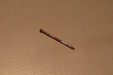 the edge connector - another panel pin !. The internal speaker
didn't work because of a faulty mini jack socket at the back. I reckon the
previous owner took the audio board out (thinking that was where the
speaker fault was)..and a box of pins fell into the open radio….must
have been a comedy moment all those years ago and and I assume he
then gave up trying to fix it. Amazingly it came back to life
OK….yes, another radio bodger trying to catch me out. He must have
been a CB / Freebander as the heterodyne crystals were dotted about
all over the HF spectrum. It has all the low ham bands but only one
10m and one just above 30MHz. That probably explains his lack of
repair skills.
the edge connector - another panel pin !. The internal speaker
didn't work because of a faulty mini jack socket at the back. I reckon the
previous owner took the audio board out (thinking that was where the
speaker fault was)..and a box of pins fell into the open radio….must
have been a comedy moment all those years ago and and I assume he
then gave up trying to fix it. Amazingly it came back to life
OK….yes, another radio bodger trying to catch me out. He must have
been a CB / Freebander as the heterodyne crystals were dotted about
all over the HF spectrum. It has all the low ham bands but only one
10m and one just above 30MHz. That probably explains his lack of
repair skills.
The receiver worked for a few hours then died, but OK on TX. As the radio still worked on TX the fault was quickly traced to the transistor that follows the IF filters on the receive path, after removing it my PEAK transistor tester said 'no component connected', it had just died. Replaced with a BF194 and back working - until yet nother transistor failure a few hours later on the RF board - this time it was the heterodyne oscillator. Yet again the transistor tester showed it had died. Very odd to have 2 silicon transistor failures in the same radio within hours of each other - what goes on with these Japanese 2SC devices from the 70's??. Put in a BSX20 and its fixed.
Something quite bad must have happened to this radio and its a credit to Yaesu that it survived. I think someone must have plugged the wrong 12 pin mains lead in and put a high voltage on the 14V DC line..both the LEDs on the front panel are dead (and very had to get at). After changing yet another failed transistor (number 3) - one of the FETs on the IF board - the radio has now run for over 9 months without apparent issue.
My technique to quickly locate the IF and RF faults on this radio was to use my RigExpert antenna analyser with an RF choke across its output..this can be quickly set to the 2nd and 1st IF frequency and moved near the parts of the radio to isolate the fault.
 The
Noise Blanker is an area where Yaesu constantly fiddled with designs
- there are quite a few blanker board variants. Early ones were
useless and the Drake 4 line blanker was far superior In this radio I
thought Mr Bodger had
been at the blanker PCB, but a few mins research revealed the mods were done by
Yaesu.
The
Noise Blanker is an area where Yaesu constantly fiddled with designs
- there are quite a few blanker board variants. Early ones were
useless and the Drake 4 line blanker was far superior In this radio I
thought Mr Bodger had
been at the blanker PCB, but a few mins research revealed the mods were done by
Yaesu.
Yaesu also kept with a high mic impedance for the first generation FT101's..and changed to low impedance for the 101Z/ZD..the mics look the same though..so always read the label !
I changed some rough looking caps on the audio board. Elna capacitors are pretty reliable but some of the 220uF caps were only 16V - close to the 14V that I measured on the board. Modern 25V ones are the same size so I put those in. The red mylar capacitors on the AF board are very prone to cracking and I changed most of those for new ones. Grounding on the AF board is also critical to stop any audio hum, the edge connector pins on my 101 were very dirty and the hum came and went as I moved the AF board. I suspect some parts of the edge connector were corroded by the rusty pin that was jammed in it for years - a careful clean fixed it. As with other radios I re-sprayed the case and bezel to my normal standard, flat the old paint with wet / dry and then several coats of auto grey undercoat before the top coats. The colours are very close to KW radio gear, so I used my stock of paint and defy anyone to see the subtle differences (Ford Polar Grey and Ford Dove Grey). Loads of contacts on 80m and 40m. Looks fabulous now and not seen many this clean. I had a look at some of the older FT101s on eBay, some described as in good cosmetic condition look really rough with faded lettering and marked front panels - now look at this one.
 April 2018 update
- Although I thought the radio was working well, there was a
niggling low carrier drive in TUNE on all bands (no more than 10W). I thought this was an alignment
issue as I could just about get 100W SSB peak - but only if I
turned the mic gain right up. I checked that the 3 valves were OK
and all voltages were in spec. It took
some careful detective work to get to the bottom of this. The first place
the TUNE carrier signal (derived from the AM/CW carrier crystal) goes is
into the first TX mixer (part of PB1180) along with the VFO. Both the
carrier and VFO levels into this mixer where good at 0.6 - 0.8V peak
on my scope
but the output of the mixer in either TUNE or SSB was much lower than I would
expect. After taking the PB1180 screened module apart it was clear someone
had been in there before me - its impossible to know what they were
trying to do as its very hard to get the bottom of the
PCB without major work desoldering the screened box. Mr Bodger had burnt wires and got solder blobs
everywhere. In the end my proof would probabaly have to be
another PB1180 module. This was spot on and another one restored both carrier
and SSB drive with much lower mic gain. I extricated the single
TX mixer transistor from the old module and it tested OK, so Mr Ham
Bodger must have caused some damage to the PCB...not worth any more
effort so I'll never know.
April 2018 update
- Although I thought the radio was working well, there was a
niggling low carrier drive in TUNE on all bands (no more than 10W). I thought this was an alignment
issue as I could just about get 100W SSB peak - but only if I
turned the mic gain right up. I checked that the 3 valves were OK
and all voltages were in spec. It took
some careful detective work to get to the bottom of this. The first place
the TUNE carrier signal (derived from the AM/CW carrier crystal) goes is
into the first TX mixer (part of PB1180) along with the VFO. Both the
carrier and VFO levels into this mixer where good at 0.6 - 0.8V peak
on my scope
but the output of the mixer in either TUNE or SSB was much lower than I would
expect. After taking the PB1180 screened module apart it was clear someone
had been in there before me - its impossible to know what they were
trying to do as its very hard to get the bottom of the
PCB without major work desoldering the screened box. Mr Bodger had burnt wires and got solder blobs
everywhere. In the end my proof would probabaly have to be
another PB1180 module. This was spot on and another one restored both carrier
and SSB drive with much lower mic gain. I extricated the single
TX mixer transistor from the old module and it tested OK, so Mr Ham
Bodger must have caused some damage to the PCB...not worth any more
effort so I'll never know.
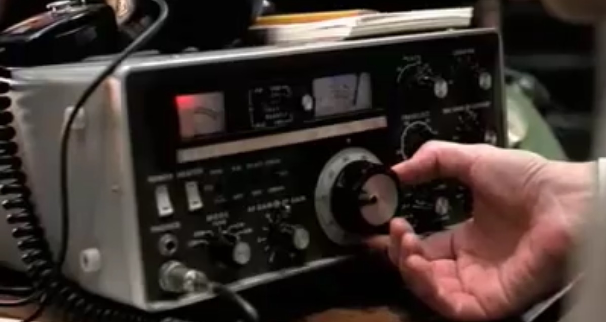
The FT101 makes an appearance in Independence Day : Resurgence (2015)...made me laugh out loud in the cinema when I saw it...it was set to 20m. I thought we had been using alien technology for 20 years in this film..you see folks..even aliens couldn't match the FT101 and a Shure 444 !. The 2008 Film 'The Bank Job' has one in (RH pic) and yet another 101 also pops up in Die Hard 3 when Bruce Willis tries to call the Coast Guard from the ship near the end of the film

Some end up looking this !!!!!!!!!!!...described as 'good condition'. On eBay in Jan 2018....not for me
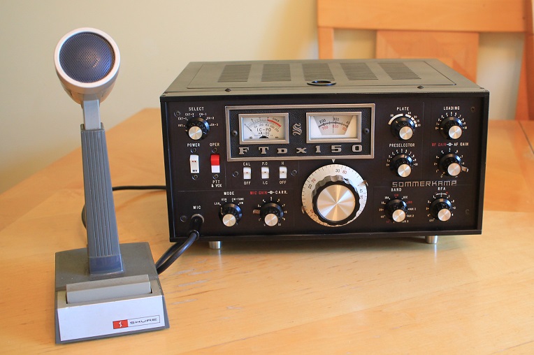
Sommerkamp FTdx150 / Yaesu FTdx100
Took delivery of this one in August 2017 - very clean, not abused and mostly working!. This is one of the worst radios for access to components I have worked on. Yaesu quickly moved to plug in boards after this. The IF strip is under a large screening can that is near impossbile to remove, and the RF stages are under the bandswitch. The HV caps are also totally inaccessible without open heart surgery. There is no service mauaul or PCB layout info and the circuit diagams in the manual did not accurately match what I found in the radio. Having said all that after a thorough relay clean and replacement of a very leaky AGC amplifier transistor it now works - very little wrong. I had to buy some NPN germanium transistors as they are the one component I could not find in my stock. The leakage was so bad the AGC release time had gone very short making SSB audio sound awful. As usual I started with a thorough 'deep' clean (especially the dreaded relays), check over and finally repainted the case and bezel in period correct satin black - looks nearly new now. Apparently the terms ' clarifier' and 'RIT' were not in common usage in Japan..so they called IRT 'RFA' or 'Receive Frequency Adjustment'. 80m SSB reports have been very complimentary and loads of audio drive with the Foster 'ICE' microphone that came with it. The lower power 6JM6 finals mean it runs quite cool as well - I'm quite smitten with this little radio!
The all solid state receiver sounded surprisingly good after I rolled a little bit of treble off the audio. On my Drake LS it sounded very harsh, as I like a mellower sound I put a few nf across the top of AF gain pot and it sounded far far better. Unlike the old tube kit the sensitivity doesn't drop off much on the higher bands and the VFO is rock stable straight away. The single IF crystal filter does not have a brilliant shape factor, but its more than adequate for casual operation. This was a super little rig (espccially for mobile operation) for the time (1966-69), when you consider Drake , Swan and KW stuck entirely with all tube radios well into the mid 70s.
The CAL switch also caused a little problem - as well as turning the calibrator on it also switches the ANTENNA changeover relay to TX (really!!!) . This means that the receiver is disconnected from the antenna making it easier to hear the cal signal. On my radio the switch was dirty and would not allow the ANTENNA changeover relay to work properly in the CAL OFF position..a quick switch clean cured this and normal operation was restored
 If by some fluke you are reading this and working on one of
these..check that the AGC timing capacitor is between the base and
collector of the AGC amplifier TR204, on mine it was between the base
and ground, its under the PCB and easy to move. Its a vast improvement
and actually shown that way in the later FTdx100 schematic (20uF).
If by some fluke you are reading this and working on one of
these..check that the AGC timing capacitor is between the base and
collector of the AGC amplifier TR204, on mine it was between the base
and ground, its under the PCB and easy to move. Its a vast improvement
and actually shown that way in the later FTdx100 schematic (20uF).
The capacitor must have been moved at some point in the FTdx100 production run and I would have thought this FTdx model should have had this change. Perhap.the person on the production line was working from an old drawing. Anyhow, I increased the value to 47uF to sound better on SSB.
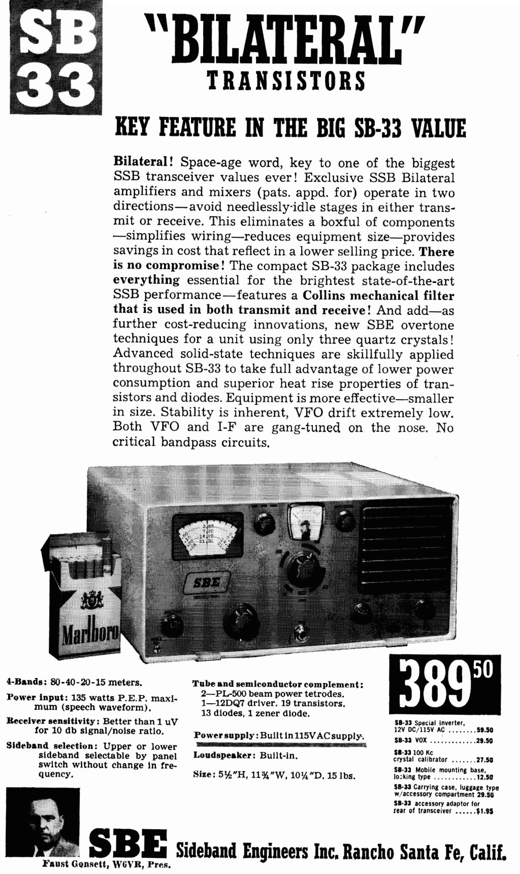
It appears that very few Yaesu FT100 models were officially sold in the US..folklore has it that the SBE Company (Sideband Engineers - owned by Gonsett) claimed the Yaesu radio infringed some copyright or design ideas from the similar US made SBE-33 and SBE-34. The SBE-33 may have been the very first hybrid HF transceiver and was released in 1963. The improved SBE-34 was also a hybrid transceiver wuth built in AC/DC power supplies in a compact package and came out about the same time as the FT100 in 1966. In an effort to compete SBE even moved production to Japan for the SBE-35 and 36 models (nixie tube display!!), but the competition was too strong and they reverted to the CB market for a few years after 1970. It seems the SBE story follows a familiar ham radio theme - one in which the initial innovation was not followed up with a mature mass produced product that could be sold round the world. To my knowledge SBE products were never sold in the UK and very few hams around now have ever heard of them.
FT101Z/ZD Collection
My 1979 FT101Z MK1 came out of retirement in 2002..and worked straight out of the box. It has AM fitted - there was a MK0 which had no AM position on the function switch. The AM receive is dreadful as Yaesu use the SSB filter in that mode - no easy provision for an AM filter although some have put a 6KHz filter in the CW position re-wired the mode switch to have it in circuit in AM mode. Still working fine in 2020. Compared to the KW and Drake these radios are light years ahead, when you have them apart you can see the great attention to detail in the wiring and PCB board labelling. I do love the smooth audio sound of the receive on the 101ZD its absolutely superb, Yaesu really put a lot of thought into the design of this line of radios and its hard to imagine a better SSB sound. Along with the Kenwood TS830 / 530 thes Yaesu FT101ZD/901/902DM are pretty much at the pinnacle of hybrid HF radio design. The FT102 was the very last hybrid Yaesu radio and although a superb performer is not quite so easy to work on. Every ham must try one of these !
I was offered another FT101ZD in 2003 that had also been little used, it also worked OK after many years out of service. This 101ZD had a CB crystal in place of one of the 10m band positions but it had not been abused - The PA still gives good power out and there is no evidence of stress in the PA compartment. Although these MK1 radios are not shown as FM capable, the FM board can be fitted (works in the AM position) - a squelch control needs to be added. In this example a small preset variable pot has been added to the connector on the FM board that would normally go to the control..so its preset and works fine. It can only have been used on CB for a short period in the late 70's. Its only fault was an intermittent 'clarifier' control which turned out to be one of the pesky little 12v DIP relays..a quick repair.
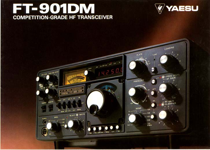
FT902 DM
My next acquisitionon from another mate in 2003 was a pristine FT902DM (similar to FT901DM) complete with Speaker and ATU. This is a fabulous bit of kit which has been my main rig. The receiver is still in the top 30 for close in dynamic range on the Sherwood website and I have never found a single weakness in the RX performance even on 10m. Yaesu pushed the boat out with the 902DM and it was one of the very best 'hybrids' ever produced - and at the time of its release one of the very best receivers (billed as a contest capable rig). It has a keyer, CW filter, IF width, Proper AM and FM, Audio Filter, Notch, Memory, Tune Up timer etc...oh.. and its very heavy!
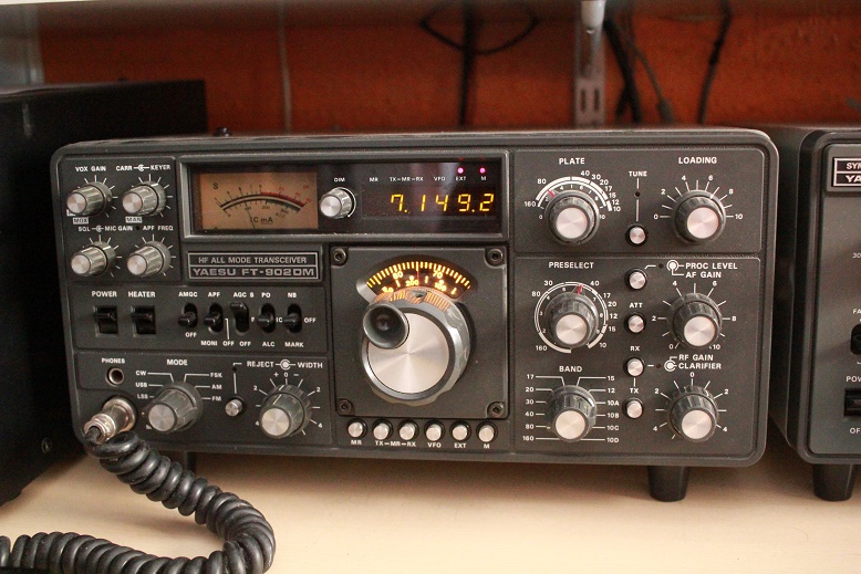
I quickly added the FV901 digital VFO..only 100Hz steps but dead stable, the FTV transverter followed and then I started to run out of room. Driving an AL811 linear this set up has become my main station..perfect.
I have had remarkably few problems with any of my Yaesu gear - a testament to the design, build quality and the quality of components used. The small black 12 V DIP relays appear to be a week spot wherever they get used on ham gear. I have had 2 relay failures - one on the speech board in the FT902 and one in the clarifier of an FT101ZD - they only cost a few pennies to replace. In 2019 The FT902 developed a fault that made the receiver noisy - traced to the diode mixer on the RF board..easy fix
Yaesu FR50B Receiver
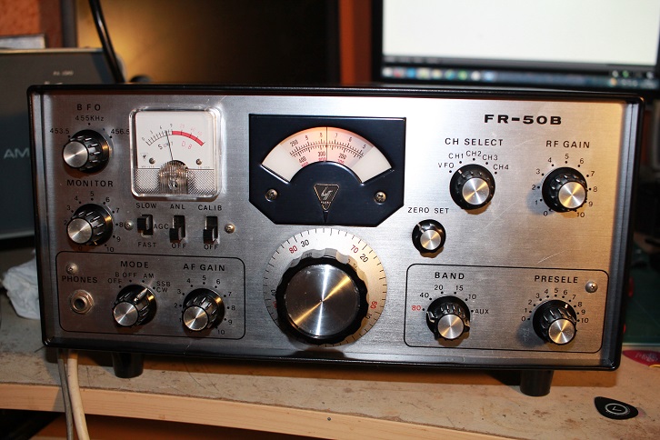
Another bit of kit that came to me through a Silent Key clearance. This is one of Yaesu's earliest receivers as part of their mid 60's 'novice' set up. Its a pretty simple design and very easy to work on and they are quite rare in good or working condition. The radio uses the dreaded 'switched VFO' that does away with a crystal premix arrangement and saves money..same as the Swan 350 / 500 and KW Atlanta..makes alignment very tricky and a bit temperamental. Before agreeing to buy this RX (for not much money) I downloaded the manual and checked the web for any obvious problems. All the pictures showed 2 simple (and small) mechanical filters in series in the IF, and no one had reported problems..oh how wrong can you be!.
When I got the RX home and opened it up I saw to my chagrin that unlike any internet pictures it had a large Kokusai mechanical filter (as used in my KW gear)..where the hell did that come from??. It was clearly a factory fit and I suspect it was a transition FR50B from the earlier FR50 model which I suspect had this filter installed..damn!...and of course it was as dead as a dodo . As with my KW gear I bypassed the filter with 1000pf and found I had a working radio. Luckily I have spare Kokusai Mech filters and a few Murata ceramic SSB filters at 455KHz. In the end I fitted a Murata CFJ455 and appropriate matching transformers. I also like the variable BFO, no need to worry about carrier crystals !. Summer 2018 update, as I needed the Murata SSB filter for other projects I installed a Toko AM filter instead. The TOKO CFMQ 001A units are less than £3 from JABDOG.com and come with tuned circuits and a ceramic resonator in a nice litle unit. The As expected FR50 now sounds very W I D E on SSB !, but 80m AM is brilliant
The internal speaker is truly awful, but I had a shock when I attached a Drake MS4 - the audio sounded really great - A check of the schematic revealed that the designers had put some negative feedback around the valve output stage - sounds really 'smooth' and easy to listen to. I also noted that even after alignment it was bit low on IF gain, i used the old trick of a few pf across the IF transformers and things improved, and its a very quiet receiver with the antenna unplugged..I listened to it every day for a week on 80m..the reported VFO drift was acceptable after warm up as well
The Cosmetics were next - the case was a bit marked in places and had some rust spots - out with the wet / dry sandpaper and Hammerite 'satin' black. This is how I paint the Drakes as well...4 light coats give a near flawless finish. Cleaned all the knobs and it looks and sounds great...time to get its big brother the FR100 !
Sommerkamp FT277ZD / FT101ZD MK3
Came to me through the local radio club as part of a silent key sale - The club noted it had been extensively modified and whilst it powered up and put out some RF power in 'Tune', the internal speaker was missing and no further testing was possible. There was a tin box hanging off the back connected to the PA fan and a lot of scribbled documents relating to complex mods
Once home on the bench I set about working out what its late owner had done - or more accurately tried to do. FT101ZDs can have either an FM or AM board fitted - but not both. Our late colleague decided he wanted both options and set about achieving his aim. He managed to screw the 2 boards beside each other, one had the correct connectors but the other had to be wired in some sort of parallel arrangement. He then had to fashion an AM/FM switching mod so added another push button and LED on the front panel (above the Clarifier switches)
He also had a bright idea - In AM mode perhaps he could use the wider 455KHz ceramic filters off the FM board to also drive the AM detector on the AM board?..this gets around the normal use of the narrow 9MHz SSB filters in AM mode (a drawback with AM on these radios). So he tapped into the FM board just before the discriminator and then tapped into the AM board before just before the AM detector (the AM board operates at the 9 MHz IF)...but I worked out what happened next..there was insufficient 455KHz IF gain to drive the AM detector properly, so - yet another bright idea ; use part of an old AM transistor radio IF strip (I’m not kidding - its in the picture!)…nowhere to put it ? - so remove the internal speaker and leave this funny extra IF strip hanging in the case. What a friggin' mess
None of this worked and probably never did. SSB seemed to be OK so I removed the worst parts of the conversion to test the rig and re-installed the speaker. After a few hours I ended with correct operation on SSB and FM only. The PA fan mod was so that the fan only came on with heaters..I took it out..after all its not a noisy fan.
After verifying I had a working radio I set about removing the rats nest of wiring between the 2 boards and the radios wiring harness. What a mess - took me 5 hours to clean up the rig at each step referring to the service manual and 2 other FT101ZD's. Along the way I learnt that the FM boards have 2 variants (not documented), and the RF unit connections (coloured cables) are reversed on the MK III unit.. He had even hacked into the PCB tracks on the AM board
Pic above shows the radio all restored to original condition. Quite why our late friend embarked on this complex and foolhardy mod is something I will never know. After a touch up alignment it works great on SSB, but he probably came close to ruining a perfectly fine radio..a lesson there somewhere. Radio ham bodgers and twiddlers - you've got to love them...maybe not
June 2020 UPDATE - Out of the blue the radio started playing up, sitting in the shack ready for a weeks operation on my vintage radio net it went ito TX all by itself. A few mins of knob twiddling verified that the vox curcuit was randomly putting it into transmit with no mic and all vox controls on zero. I had the radio apart in a few mins and looked around the vox circuit ( a Quad op amp). For no good reason one of the output pins was changing state every few secs. With no other obvious issue I removed the AF board, took out the IC (MC3403) and put a holder in. Searching the net showed an LM324 as a suitable replacement and I had one in stock. Put the board back and problem solved..weird to have yet another semiconductor failure . I also resolved 2 other issues that had niggled me for a while - the first was a 100Hz error on the digital display. I tracked this down by listening to the TX on a local receiver and studying the way the radio works, there was nothing on the web.
The give away was that on USB the radio would transmit zero beat with the display reading correctly, but was clearly 100Hz out on LSB. The display logic has to account for the carrier oscillator as you switch from USB to LSB, if the carrier osc is off frequency the display will read wrong. The exact offsets are in the firmware of the counter IC and cannot be changed so a quick twiddle of the LSB carrier Osc (on the AF board) solved the problem. Earlier versions of the 101ZD used a more complex counter with a lot of logic and had some DIP switches to adjust the offset if required - not so on the MK3.
The ALC meter was reading upscale on TX with no audio - a quick search of the forums revealed that my buddy G3YRO had replied to someone with an ALC issue and that VR01 on the IF board adjusted the ALC reading, again a quick twiddle and the meter was zeroed and reads correctly (this is not documented in the service manual)
Yaesu HT capacitors 'Orange Gunk'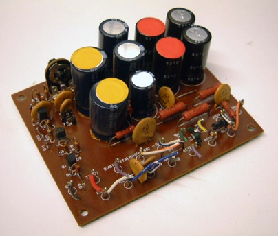
Quite a few auction sites and websites talk about the Yaesu HT capacitors 'Orange gunk or goo' - and point to the fact they are leaking all over the PCB and must be changed. Although there is no harm in changing caps (and the EHT ones probably should be changed), this is misleading ; the Orange gunk is not the caps leaking its the cement that Yaesu used to hold the caps on the PCB - they probably didn't need it but they were very thorough on the these radios. Its especially visible on the 'Rectifier A' board..so don't rush to change them when you see it
Noisy RX FT902
In 2019 I began to notice the receiver was becoming noisy
although not really down on sensitivity. Easier to notice on the higher
bands where it was hard to hear the band noise..and still noisy with the
antenna unplugged. I quickly isolated the fault to the frontend /
mixer RF board (PB2154A) by substituting it with one from a late 101ZD.
It then took me a few hours to find the problem. I initally thought the
front end MOSFET was the culprit, but removing it made no difference at
all!. Switching the VFO to EXT stopped the noise so it wasn't the FET
following the balanced mixer. Suspicion quickly fell on the 4 diodes in
the mixer itself. On some PB2154A boards the 4 diodes are in one
component block (as in this picture), but on mine there are 4 discrete
components. Although they are a bit fiddly to remove I replaced all 4
with BAT85 diodes and the noise was gone.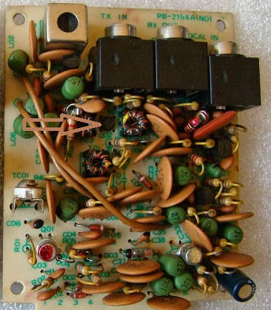
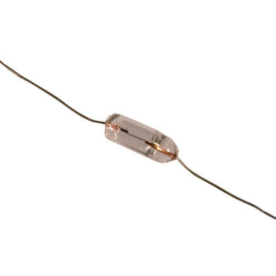
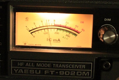
S Meter Bulbs FT902
Changing the S Meter bulbs on the FT902 is a really fiddly job. The bulbs in most variants of the radio are small axial filament bulbs rated at 8V. Getting to them is another matter..hee hee !. First the front panel must be removed - I had to use the workshop manual to work out how to do this. Remove the case and ALL the knobs (you will need a small screwdriver for the concentric knobs)..next the VFO must be removed - this requires the removal of the counter board and the bracket holding the frequency display. THEN take out the 4 allen key bolts that hold the VFO in, and start to ease it out..THEN you must release the VFO earth strap (this really caught me out)
.
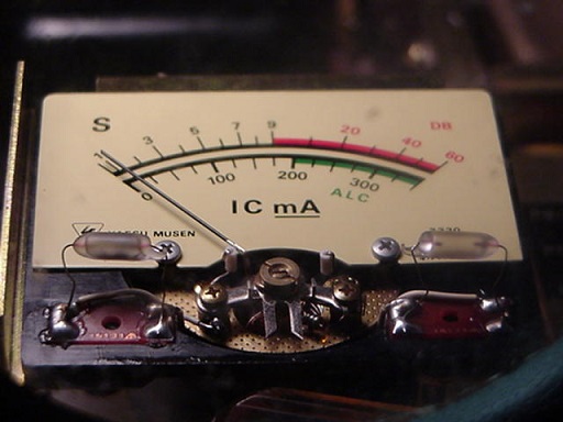
On my one the VFO earthing strap was on the bottom right screw at the front of the VFO case and the wire disappeared into the bottom of the radio - this is where I discovered a rare Yaesu error - the earthing strap should be on a solder tag under one of the many screws..but mine was soldered to a lug on the underside of chassis..once removed all was OK and I got the VFO out (a tight fit). The bulbs are actually inside the meter housing which you prise off - and the two bulbs are small - even smaller than my replacement ones - in fact in my 902 they are 2 different sizes. Its never been apart so must have been built like that.
 After reflection over a coffee, it looked like a very tight fit
to get my bulbs inside the meter - and I could never face taking the
radio apart again if they failed. I hit upon another solution. There is
room to slide a bulb in above the meter without taking half the
radio to bits - so I put one of my bulbs in a clear heatshrink sleeve
(so both wires came out one end) and slid it in to the small gap between
the meter and the front panel - wired it to the 8V supply (blue wires)
and voila. Not quite as sexy to look at but works fine and is an
invisible mod.
After reflection over a coffee, it looked like a very tight fit
to get my bulbs inside the meter - and I could never face taking the
radio apart again if they failed. I hit upon another solution. There is
room to slide a bulb in above the meter without taking half the
radio to bits - so I put one of my bulbs in a clear heatshrink sleeve
(so both wires came out one end) and slid it in to the small gap between
the meter and the front panel - wired it to the 8V supply (blue wires)
and voila. Not quite as sexy to look at but works fine and is an
invisible mod.
IMPORTANT - the countersunk screws holding the front panel on may have washers under them..BUT ONLY THE TOP SCREWS - there are no washers on the two bottom screws. The front panel is a very precise fit and if not put back properly you may find the right hand push buttons bind a little (you can push them in but they stay in!)..Yaesu puts the washers in to ensure the front panel fits OK..if you put washers under the bottom front panel screws it may make the push switches stiff..only a mm or 2 !!..I reckon its a manufacturing error that needed a bit of adjustment . Well that was a happy 4 hours !
Connect with me today
Call me on 44 (0)7970 190437